


Troubleshooting and ServiceTeledyne API – Model T300/T300M CO Analyzer
Teledyne Analytical Instruments 253
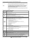
WARNING
MESSAGE
FAULT CONDITION POSSIBLE CAUSES
SAMPLE PRES
WARN
Sample Pressure is <10 in-Hg or
> 35 in-Hg
Normally 29.92 in-Hg at sea level
decreasing at 1 in-Hg per 1000 ft of
altitude.
If sample pressure is < 10 in-hg:
Blocked particulate filter
Blocked sample inlet/gas line
Failed pressure sensor/circuitry
If sample pressure is > 35 in-hg:
Pressurized sample gas. Install vent
Blocked vent line on pressurized sample/zero/span gas supply
Bad pressure sensor/circuitry
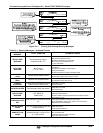
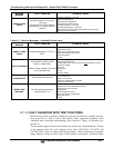
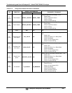
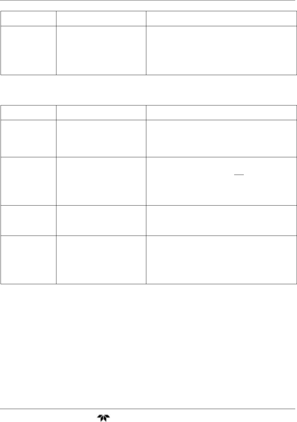
Table 13-1: Warning Messages – Indicated Failures (cont.)
WARNING
MESSAGE
FAULT CONDITION POSSIBLE CAUSES
SAMPLE TEMP
WARN
Sample temperature is < 10
o
C or >
100
o
C.
Ambient temperature outside of specified range
Failed bench heater
Failed bench temperature sensor
Relay controlling the bench heater
Failed relay board
I
2
C bus
SOURCE WARNING
Occurs when CO Ref is <1250
mVDC or >4950 mVDC.
Either of these conditions will result
in an invalid M/R ratio.
GFC Wheel stopped
Failed sync/demod board
If status LEDs on the sync/demod board ARE flashing the cause is
most likely a failed:
IR source
Relay board
I
2
C bus
IR photo-detector
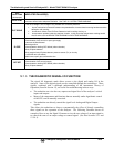
SYSTEM RESET
The computer has rebooted.
This message occurs at power on. If you have not cycled the power
on your instrument:
Failed +5 VDC power,
Fatal error caused software to restart
Loose connector/wiring
WHEEL TEMP
WARNING
The filter wheel temperature is
controlled at 68 2
°
C
Blocked cooling vents below GFC Assembly. Make sure that
adequate clear space beneath the analyzer.
Analyzer’s top cover removed
Wheel heater
Wheel temperature sensor
Relay controlling the wheel heater
Entire relay board
I
2
C bus
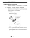
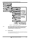
12.1.2. FAULT DIAGNOSIS WITH TEST FUNCTIONS
Besides being useful as predictive diagnostic tools, the test functions viewable from the
front panel can be used to isolate and identify many operational problems when
combined with a thorough understanding of the analyzer’s Theory of Operation (see
Section 13).
The acceptable ranges for these test functions are listed in the “Nominal Range” column
of the analyzer Final Test and Validation Data Sheet (GFC7001T, P/N 04307 and
GFC7001TM, P/N 04311) shipped with the instrument. Values outside these acceptable
ranges indicate a failure of one or more of the analyzer’s subsystems. Functions whose