


CommunicationsTeledyne API – Model T300/T300M CO Analyzer
Teledyne Analytical Instruments 151
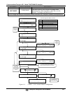
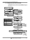
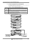
Make appropriate cable
connections
Connect your analyzer either:
via its Ethernet or USB port to a PC (this may require a USB-to-RS232 adapter for your PC; if so, also
install the software driver from the CD supplied with the adapter, and reboot the computer if required), or
via its COM2 port to a null modem (this may require a null modem adapter or cable).
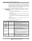
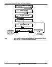
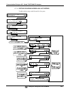
Specify MODBUS software
settings
(examples used here are for
MODBUS Poll software)
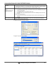
1. Click Setup / [Read / Write Definition] /.
a. In the Read/Write Definition window (see example that follows) select a Function (what you wish
to read from the analyzer).
b. Input Quantity (based on your firmware’s register map).
c. In the View section of the Read/Write Definition window select a Display (typically Float Inverse).
d. Click OK.
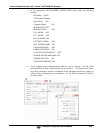
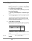
2. Next, click Connection/Connect.
a. In the Connection Setup window (see example that follows), select the options based on your
computer.
b. Press OK.
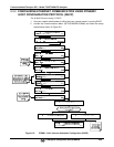
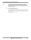
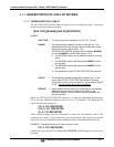
Read the Modbus Poll Register Use the Register Map to find the test parameter names for the values displayed (see example that
follows). If desired, assign an alias for each.
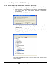
Example Read/Write Definition window:
Example Connection Setup window:
Example MODBUS Poll window: