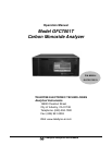
Model GFC7001T Carbon Monoxide Analyzer
Teledyne Analytical Instruments iii
INFORMATION ABOUT THE SPECIFIC CONFIGURATION OF YOUR
MODEL GFC 7001T CARBON MONOXIDE ANALYZER
Selected Versions of the Model GFC 7001T
MODEL GFC 7001T— STANDARD VERSION
This Model GFC7001T CO Analyzer is a touch screen version designed for analyzing the CO concentration in a
background gas specified by the customer. It has a minimum settable range of 0-1 ppm and a maximum settable
range of 0-1000 ppm. The standard version is designed for positive pressure applications. The analyzer may have
one or two analysis ranges with or without auto-ranging as listed below. Alarm relays are included with this
version.
M
ODEL GFC 7001TA — AMBIENT PRESSURE VERSION
The Model GFC7001TA CO Analyzer is a touch screen version designed for analyzing the CO concentration in a
background gas specified by the customer. It has a minimum settable range of 0-1 ppm and a maximum settable
range of 0-1000 ppm. The TA version is designed for ambient pressure applications. The analyzer may have one or
two analysis ranges with or without auto-ranging as listed below. Alarm relays are an optional feature and if
included, that option will be checked below.
M
ODEL GFC 7001TU — ULTRA LOW RANGE VERSION
The Model GFC7001TU CO Analyzer is a touch screen version designed for analyzing trace CO concentrations in
a background gas specified by the customer. It has a minimum settable range of 0-100 ppb and a maximum settable
range of 0-100 ppm. The TU version is designed for positive pressure applications. The analyzer may have one or
two analysis ranges with or without auto-ranging as listed below. Alarm relays are an optional feature and if
included, that option will be checked below.
P
OWER REQUIREMENTS
This Model GFC 7001T is configured to operate from the following AC Power source:
100-120 VAC 60 Hz 220-240 VAC 60 Hz 100V 60 Hz
100-120 VAC 50 Hz 220-240 VAC 50 Hz 100V 50 Hz
A
NALOG OUTPUT SIGNALS
Analog output signals are available at A1 and A2 on the rear panel. This instrument is configured with the
following analog outputs:
A1: 4-20 mA
A2: 0-5 V A2: 4-20 mA
R
ANGE MODE
The analyzer can be designed with a single or dual analysis ranges with auto-ranging or dual independent ranges.
This analyzer is configured with the following range mode:
Single Range:
Dual Range/Auto-ranging: Dual Range/Independent:
Low Range: Low Range:
High Range: High Range:


