


Troubleshooting and ServiceTeledyne API – Model T300/T300M CO Analyzer
Teledyne Analytical Instruments 275
1. Check for power to the motor by measuring between pins 1 and 3 on the connector
feeding the motor.
For instruments configured for 120 or 220-240VAC there should be
approximately 88 VAC for instruments configured for 100VAC, it should
be the voltage of the AC mains, approximately 100VAC.
2. Verify that the frequency select jumper, JP4, is properly set on the relay board.
For 50 Hz operation it should be installed.
For 60 Hz operation may either be missing or installed in a vertical
orientation.
3. If there is power to the motor and the frequency select jumper is properly set then
the motor is likely bad.
See Section 12.6.2 for instructions on removing and replacing the GFC
assembly that the motor is bolted to.
12.5.7.5. IR SOURCE
The IR source can be checked using the following procedure:
1. Disconnect the source and check its resistance when cold.
When new, the source should have a cold resistance of more than 1.5 Ohms
but less than 3.5 Ohms.
If not, then the source is bad.
2. With the source disconnected, energize the analyzer and wait for it to start operating.
Measure the drive Voltage between pins 1 and 2 on the jack that the source
is normally connected to; it should be 11.5 ± 0.25 VDC.
If not, then the problem is with the wiring, the relay board, or the +12V
power supply.
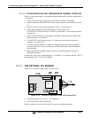
3. If the drive voltage is correct in step 2, then remove the source from the heat sink
assembly (2 screws on top) and connect to its mating connector.
Observe the light being emitted from the source.
It should be centered at the bottom of the U-shaped element.
If there is either no emission or a badly centered emission, then the source is
bad.
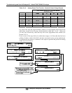
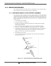
12.5.7.6. PRESSURE/FLOW SENSOR ASSEMBLY
The pressure/flow sensor PCA, located on the top of the absorption bench, can be
checked with a voltmeter using the following procedure which, assumes that the wiring
is intact, and that the motherboard and the power supplies are operating properly:
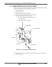
1. For pressure related problems:
Measure the voltage across C1 - it should be 5 ± 0.25 VDC.
If not, then the board is bad.
Measure the voltage across TP4 and TP1.
It should be 4500 mV ±250 mV.