Getting StartedTeledyne API – Model T300/T300M CO Analyzer
Teledyne Analytical Instruments 76
for calibrating instruments that have valve options.
3.4.4.1. INTERFERENTS FOR CO MEASUREMENTS
It should be noted that the gas filter correlation method for detecting CO is subject to
interference from a number of other gases that absorb IR in a similar fashion to CO.
Most notable of these are water vapor, CO
2
, N
2
O (nitrous oxide) and CH
4
(methane).
The GFC7001T/GFC7001TM has been successfully tested for its ability to reject
interference from of these sources, however high concentrations of these gases can
interfere with the instrument’s ability to make low-level CO measurements.
For a more detailed discussion of this topic, see Section 13.2.1.3.
3.4.4.2. INITIAL CALIBRATION PROCEDURE
The following procedure assumes that:
The instrument DOES NOT have any of the available calibration valve or gas inlet
options installed;
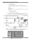
Cal gas will be supplied through the SAMPLE gas inlet on the back of the analyzer
(see Figure 3-4)
The pneumatic setup matches that described in Section 3.3.2.1.
V
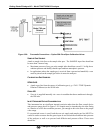
ERIFYING THE GFC7001T/GFC7001TM REPORTING RANGE SETTINGS
While it is possible to perform the following procedure with any range setting we
recommend that you perform this initial checkout using following reporting range
settings:
Unit of Measure: PPM
Analog Output Reporting Range: 50 ppm
Mode Setting: SNGL
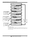
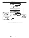
While these are the default setting for the GFC7001T/GFC7001TM Analyzer, it is
recommended that you verify them before proceeding with the calibration procedure, by
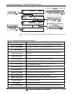
pressing:


