


SetupTeledyne API – Model T300/T300M CO Analyzer
Teledyne Analytical Instruments 117
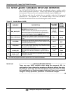
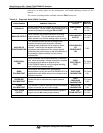
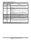
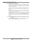
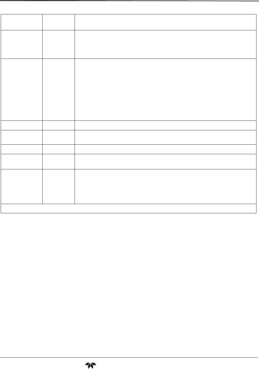
Table 5-5: DIAG - Analog I/O Functions
SUB MENU
OUTPUT
CHANNEL
FUNCTION
AOUT
CALIBRATED
ALL
Initiates a calibration of the A1, A2, A3 and A4 analog output channels that
determines the slope and offset inherent in the circuitry of each output.
These values are stored and applied to the output signals by the CPU
automatically.
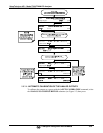
CONC_OUT_1
A1
Sets the basic electronic configuration of the A1 output (CO Concentration).
There are four options:
RANGE
1
: Selects the signal type (voltage or current loop) and level of the
output.
REC OFS
1
: Allows them input of a DC offset to let the user manually adjust
the output level.
AUTO CAL: Enables / Disables the AOUT CALIBRATED feature.
CALIBRATED: Performs the same calibration as AOUT CALIBRATED,
but on this one channel only.
CONC_OUT_2
A2
Same as for CONC_OUT_1 but for analog channel A2.
CONC_OUT_3
A3
Same as for CONC_OUT_1 but for analog channel A3 but only if either the
optional O
2
or CO
2
sensors are installed.
TEST OUTPUT
A4
Same as for CONC_OUT_1 but for analog channel A4 (TEST CHANNEL).
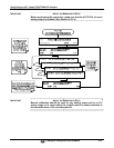
AIN
CALIBRATED
N/A
Initiates a calibration of the A-to-D Converter circuit located on the
Motherboard.
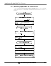
XIN1
.
.
.
XIN8
For each of 8 external analog input channels, shows the gain, offset,
engineering units, and whether the channel is to show up as a Test function.
1
Any changes made to RANGE or REC_OFS require recalibration of this output.