


Troubleshooting and ServiceTeledyne API – Model T300/T300M CO Analyzer
Teledyne Analytical Instruments 260
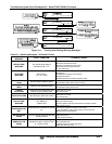
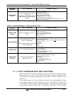
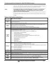
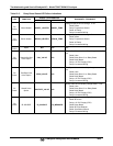
Table 12-5: Relay Board Status LED Failure Indications
LED FUNCTION
SIGNAL I/O PARAMETER
DIAGNOSTIC TECHNIQUE
ACTIVATED BY VIEW RESULT
D2
Yellow
Wheel Heater
WHEEL_HEATER WHEEL_TEMP
Voltage displayed should change. If not:
Failed Heater
Faulty Temperature Sensor
Failed AC Relay
Faulty Connectors/Wiring
D3
Yellow
Bench Heater
BENCH_HEATER BENCH_TEMP
Voltage displayed should change. If not:
Failed Heater
Faulty Temperature Sensor
Failed AC Relay
Faulty Connectors/Wiring
D4
Yellow
Spare
N/A N/A
N/A
D5
Green
Sample/Cal Gas
Valve Option
CAL_VALVE N/A
Sample/Cal Valve should audibly change states. If
not:
Failed Valve
Failed Relay Drive IC on Relay Board
Failed Relay Board
Faulty +12 VDC Supply (PS2)
Faulty Connectors/Wiring
D6
Green
Zero/Span Gas
Valve Option
SPAN_VALVE N/A
Zero/Span Valve should audibly change states. If
not:
Failed Valve
Failed Relay Drive IC on Relay Board
Failed Relay Board
Faulty +12 VDC Supply (PS2)
Faulty Connectors/Wiring
D7
Green
Shutoff Valve
Option
SHUTOFF_VALVE N/A
Shutoff Valve should audibly change states. If not:
Failed Valve
Failed Relay Drive IC on Relay Board
Failed Relay Board
Faulty +12 VDC Supply (PS2)
Faulty Connectors/Wiring
D8
Green
IR SOURCE
IR_SOURCE CO_MEASURE
Voltage displayed should change. If not:
Failed IR Source
Faulty +12 VDC Supply (PS2)
Failed Relay Board
Failed IR Photo-Detector
Failed Sync/Demod Board
Faulty Connectors/Wiring