


Getting StartedTeledyne API – Model T300/T300M CO Analyzer
Teledyne Analytical Instruments 63
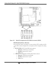
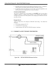
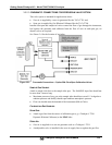
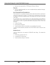
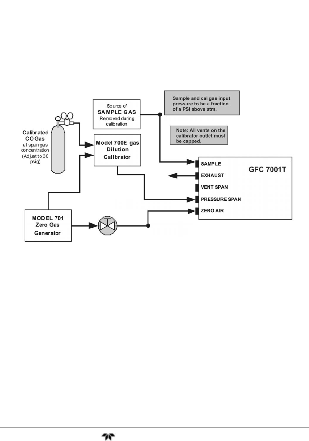
3.3.2.3. PNEUMATIC CONNECTIONS FOR ZERO/SPAN VALVE OPTION
This valve option is intended for applications where:
Zero air is supplied by a zero air generator like the TAI’s T701 and;
Span gas is supplied by Gas Dilution Calibrator like the TAI’s T700.
Internal zero/span and sample/cal valves control the flow of gas through the instrument,
but because the generator and calibrator limit the flow of zero air and span gas, no
shutoff valves are required.
See Figure 3-4 for the location of gas inlets.
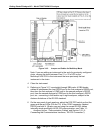
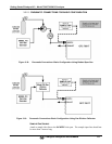
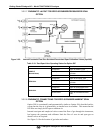
Figure 3-21: Pneumatic Connections – Option 50A: Zero/Span Calibration Valves
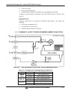
SAMPLE GAS SOURCE
Attach a sample inlet line to the sample inlet port. The SAMPLE input line should not
be more than 2 meters long.
Maximum pressure of any gas at the sample inlet should not exceed 1.5 in-hg above
ambient pressure and ideally should equal ambient atmospheric pressure.
Flow rate should meet the demand of the instrument (800 cm
3
/min).
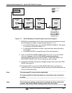
C
ALIBRATION GAS SOURCES
S
PAN GAS:
Attach a gas line from the source of calibration gas (e.g. a Teledyne’s T700
Dynamic Dilution Calibrator) to the SPAN inlet.
Z
ERO AIR:
Zero air is supplied via a zero air generator such as a Teledyne’s T701.
An adjustable valve is installed in the zero air supply line to regulate the gas flow.