


Getting StartedTeledyne API – Model T300/T300M CO Analyzer
Teledyne Analytical Instruments 50
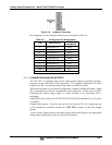
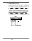
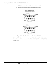
CONTROL IN
A B C D E F U
+
LOW SPAN
ZERO
CONTROL IN
A B C D E F U
+
LOW SPAN
ZERO
-
+
5 VDC Power
Supply
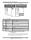
Local Power Connections
External Power Connections
HIGH SPAN
HIGH SPAN
Figure 3-12: Control Input Connector
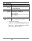
Table 3-7: Control Input Signals
INPUT # STATUS DEFINITION ON CONDITION
A
REMOTE ZERO CAL
The analyzer is placed in Zero Calibration mode. The mode field of the
display will read ZERO CAL R.
B
REMOTE SPAN CAL
The analyzer is placed in span calibration mode as part of performing a low
span (midpoint) calibration. The mode field of the display will read LO CAL
R.
C
REMOTE CAL HIGH RANGE
The analyzer is forced into high range for zero or span calibrations. This
only applies when the range mode is either DUAL or AUTO. The mode field
of the display will read HI CAL R.
D, E
& F
SPARE
Digital Ground
The ground level from the analyzer’s internal DC power supplies (same as
chassis ground).
U External Power input Input pin for +5 VDC required to activate pins A – F.
+
5 VDC output
Internally generated 5V DC power. To activate inputs A – F, place a jumper
between this pin and the “U” pin. The maximum amperage through this port
is 300 mA (combined with the analog output supply, if used).
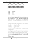
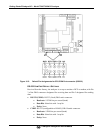
3.3.1.7. CONCENTRATION ALARM RELAY (OPTION 61) STANDARD
CONFIGURATION
The concentration alarm option is comprised of four (4) “dry contact” relays on the rear
panel of the instrument. This relay option is different from and in addition to the
“Contact Closures” that come standard on all TAI instruments. Each relay has 3 pins:
Normally Open (NO), Common (C), and Normally Closed (NC).