


Calibration Procedures Teledyne API – Model T300/T300M CO Analyzer
Teledyne Analytical Instruments 195
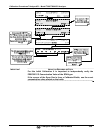
Note
It is generally a good idea to use 80% of the reporting range for that channel for
the span point calibration.
For instance, if the reporting range of the instrument is set for 50.0 PPM, the
proper span gas would be 40.0 PPM.
9.1.2. DATA RECORDING DEVICES
A strip chart recorder, data acquisition system or digital data acquisition system should
be used to record data from the serial or analog outputs of the GFC7001T/GFC7001TM.
If analog readings are used, the response of the recording system should be checked
against a NIST traceable voltage source or meter.
Data recording devices should be capable of bi-polar operation so that negative
readings can be recorded.
For electronic data recording, the GFC7001T/GFC7001TM provides an internal data
acquisition system (DAS), which is described in detail in Section 7.
APICOM, a remote control program, is also provided as a convenient and powerful tool
for data handling, download, storage, quick check and plotting (see Section 7.2.1).
9.2. MANUAL CALIBRATION
IMPORTANT
IMPACT ON READINGS OR DATA
ZERO/SPAN CALIBRATION CHECKS VS. ZERO/SPAN CALIBRATION
Pressing the ENTR button during the following procedure resets the stored
values for OFFSET and SLOPE and alters the instrument’s Calibration.
This should ONLY BE DONE during an actual calibration of the
GFC7001T/GFC7001TM.
NEVER press the ENTR button if you are only checking calibration. If you wish to
perform a calibration CHECK, do not press ENTR and refer to Section 9.2.2.
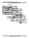
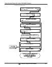
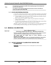
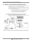
9.2.1. SETUP FOR BASIC CALIBRATION CHECKS AND
CALIBRATION
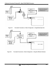
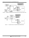
STEP ONE: Connect the Sources of Zero Air and Span Gas as shown below.