


Troubleshooting and ServiceTeledyne API – Model T300/T300M CO Analyzer
Teledyne Analytical Instruments 276
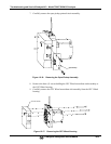
If an internal pump (option) is installed, with the pump energized, it should
be approximately 200 mV less.
If the voltage is incorrect, then S1, the pressure transducer is bad, the board is bad, or
there is a pneumatic failure preventing the pressure transducer from sensing the
absorption cell pressure properly.
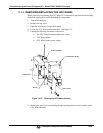
2. For flow related problems:
Measure the voltage across TP2 and TP1 - it should be 10 ±0.25 VDC.
If not, then the board is bad.
Measure the voltage across TP3 and TP1:
With proper flow (800 sccm at the sample inlet) this should be
approximately 4.5V (this voltage will vary with altitude).
With flow stopped (sample inlet blocked) the voltage should be
approximately 1V.
If the voltage is incorrect, the flow sensor is bad, the board is bad, or there is a leak
upstream of the sensor.
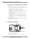
12.5.8. MOTHERBOARD
12.5.8.1. A/D FUNCTIONS
The simplest method to check the operation of the A-to-D converter on the motherboard
is to use the Signal I/O function under the DIAG menu to check the two A/D reference
voltages and input signals that can be easily measured with a voltmeter.
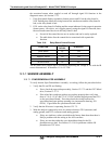
1. Use the Signal I/O function (see Section 12.1.3 and Appendix A) to view the value
of REF_4096_MV and REF_GND.
If both are within 3 mV of nominal (4096 and 0), and are stable, ±0.5 mV
then the basic A/D is functioning properly. If not then the motherboard is
bad.
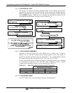
2. Choose a parameter in the Signal I/O function such as SAMPLE_PRESSURE,
SAMPLE_FLOW, CO_MEASURE or CO_REFERENCE.
Compare these voltages at their origin (see interconnect drawing, P/N 04215
and interconnect list, P/N 04216) with the voltage displayed through the
signal I/O function.
If the wiring is intact but there is a large difference between the measured
and displayed voltage (±10 mV) then the motherboard is bad.
See also Sections 5.9.1 and 12.1.3.
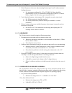
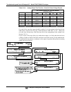
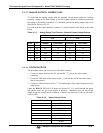
12.5.8.2. TEST CHANNEL / ANALOG OUTPUTS VOLTAGE
The ANALOG OUTPUT submenu, located under the SETUP MORE DIAG
menu is used to verify that the GFC7001T/GFC7001TM Analyzer’s analog outputs are
working properly. The test generates a signal on functioning outputs simultaneously as
shown in the following table. (See also Section 5.9.2).