


2150EX Area Velocity Flow Module
Section 5 Maintenance
5-11
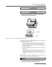
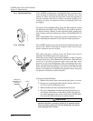
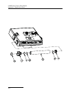
5.6.3 Sensor Cable
Inspection
Erroneous level or velocity readings may not always indicate a
fault inside the AV Sensor body. A damaged cable can affect the
operation of the sensor, particularly if the reference air tube
inside the cable is collapsed or blocked. Damaged cables cannot
be spliced or repaired.
If the AV Sensor cable is damaged, you must replace the entire
assembly, as the sensor body and cable are a factory-sealed unit.
Keep the connector clean and dry and install the cable so that it
is not at risk of damage resulting from other activity taking place
in the area. The connector can be replaced in some instances,
depending on the condition of the cable.
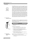
In temporary installations, do not leave cables lying around
where they may be stepped on or run over by heavy equipment.
Do not leave extra cable loose in the flow stream where it can
trap debris.
In permanent installations, cables repeatedly subjected to abuse
will fail and should be installed in conduit for protection. The
conduit must be large enough to pass the connector through, as
you cannot remove or replace it.
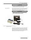
5.7 How to Obtain Service The internal components of the 2150EX System are not user-ser-
viceable. The case is completely sealed to protect the internal
components. To repair the unit, the case must be broken open
and replaced. If you think your module requires repair, contact
Teledyne Isco’s Technical Service Department.
Teledyne Isco, Inc.
Technical Service Dept.
P.O. Box 82531
Lincoln, NE 68501 USA
Phone: (800) 228-4373
(402) 464-0231
FAX: (402) 465-3085
E-mail:
IscoService@teledyne.com
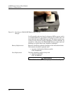
The pressure transducer, the ultrasonic transducers, cable con-
nections, and the electronic components of the AV Sensor are
encapsulated in plastic resin and are not user-serviceable. If any
part of the AV Sensor fails, it must be replaced.
Corresponding with a Teledyne Isco Technical Service Represen-
tative can often resolve the problem without the need to return
the item. If the difficulty cannot be resolved you will be issued a
Return Authorization Number (RAN) and information on
returning it to the factory.
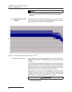
5.7.1 Diagnostics As a troubleshooting aid, many module functions can generate a
diagnostic file. With the assistance of a Teledyne Isco Technical
Service Representative, the diagnostic files can often be used to
isolate a problem.
To view a diagnostic file, connect to the site with Flowlink. View
the measurement tab of the suspect function and click on the
Diagnostics... button. The module then generates the file and
sends it to Flowlink where it is displayed as a text report.
Flowlink can also collect all of the diagnostic files while
retrieving data. The last available diagnostic files are always
kept in Flowlink’s database where they can be viewed “off-line”
at a later time. To enable Flowlink to automatically collect all
diagnostic files while retrieving the data, open the Util-
ities>Options from the menu and check the Retrieve data gets text
reports box on the 2100 tab.