


2150EX Area Velocity Flow Module
Section 2 Preparation and Installation
2-19
Observe intrinsic safety requirements regarding proximity to
external sources of potential electric or magnetic interference.
Refer to IEC 10079-14 section 12.2.2.5 on installation of cables
and wiring.
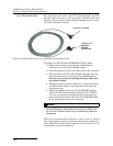
WARNING
Do not coil the interface cable; this will form an inductor
and create a hazard. The cable should be kept as short as
is practical.
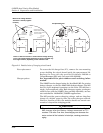
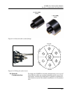
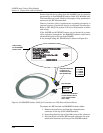
Teledyne Isco strongly recommends that you route the
interface cable through conduit between the safe and haz-
ardous areas. Two different sizes of conduit fittings are pro-
vided with the interface cable assembly (Figure 2-14).
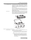
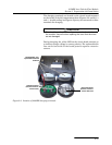
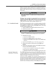
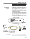
2.5.1 Installation Example The following steps may be used as a summary guide to install a
basic, permanent 2150EX system, including the 2150EX module,
the 2194EX power module, and an AV2150EX sensor. The setup
will look similar to Figure 2-3.
1. Inspect 2150EX and 2194EX module desiccant (2.4.4).
2. Install the interface cable.
WARNING
Do not coil the cable; this will form an inductor and create
a hazard. The cable should be kept as short as is practical.
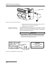
3. Assemble the system.
a. Install the 2150EX module.
b. Install the 2194EX module in the safe area.
c. Attach the AV2150EX sensor cable to the 2150EX mod-
ule (2.7).
4. Install the AV2150EX sensor in the flow stream (2.7.1).
5. Connect the interface cable between the 2150EX and
2194EX.
6. Connect the interrogation cable to the 2194EX and connect
to the site with Flowlink software.
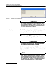
a. Create the site by Quick Connecting to the modules.
b. Set up the site and module settings.
c. Disconnect from the site and replace all protective caps.
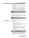
Important Information
Regarding "X" Marking
The ATEX labeling on the serial tag of the 2194EX module shows
a number ending in "X". The X marking indicates that there are
special conditions that must be met to ensure intrinsic safety, as
explained on page vi in the front of this manual.
In the case of the 2194EX, this associated apparatus does not
provide the galvanic isolation required for zone 0 installations in
accordance with IEC 60079-14 (refer to IEC 60079-14 sections
dealing with earthing of intrinsically safe circuits and installa-
tions for zone 0) when powered by an Isco AC power source.