


2150EX Area Velocity Flow Module
Section 2 Preparation and Installation
2-18
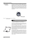
2.5 Permanent
Installations
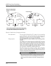
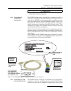
For permanent installations, the 2150EX can be powered from a
safe area by an associated apparatus, the 2194EX module. The
2194EX also serves as a network interface, with network and
RS232 communication via the top connector. The 2194EX
requires 12 or 24 volts DC, and may be powered by an Isco
910/920 series power pack, 934 NiCad battery, or 940 series lead
acid battery using power adapter cable 69-2004-451. For details
about these power supplies, see Isco’s Power Products Guide
(60-9003-092).
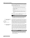
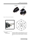
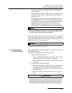
Figure 2-11 Amphenol connector pins for 12V adapter
cable 69-2004-451
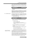
Note
Isco AC power supplies do not provide galvanic isolation in
accordance with IEC 60079-14 for Zone 0 installations.
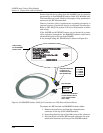
Connection to the 2194EX module requires the network interface
cable. The cable’s molded connector plug will connect to the
bottom communication port of the 2150EX module. The other end
will enter the safe area, usually via conduit.
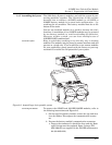
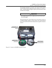
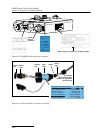
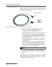
Make sure the 2150EX is secured so that it will not accidentally
fall or be swept away by flooding. Mount the 2150EX onto the EX
bottom plate (60-2004-344) for suspension over the flow stream.
Use the notched holes in the plate to insert fasteners to secure
the module to a wall, or attach a carrying handle and suspension
handle (P/N 69-2003-271 and P/N 60-1704-017), which can be
secured to a ladder rung.
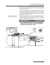
Two interface cable assemblies are available from Teledyne Isco:
75m (60-2004-337) and 150m (60-2004-338). You must cut the
cable to the appropriate length and wire it to the socket insert of
the 2194EX’s J1 interface connector (Figures 2-12 and 2-15),
which is clearly marked with the proper entity parameters. To
power one 2150EX module, the cable must be 150 meters or
shorter. To power two 2150EX modules, the cable must be 75
meters or shorter.
Pin B = +12 Volts
Pin A = Neutral
EX Bottom Plate
60-2004-344