


2150EX Area Velocity Flow System
Table of Contents
13
D.2 Planning . . . . . . . . . . . . . . . . . . . . . . . . . . . . . . . . . . . . . . . . . . . . . . . . . . . . . . . . . . D-2
D.3 Adverse Atmospheres. . . . . . . . . . . . . . . . . . . . . . . . . . . . . . . . . . . . . . . . . . . . . . . . D-2
D.4 Entering Manholes. . . . . . . . . . . . . . . . . . . . . . . . . . . . . . . . . . . . . . . . . . . . . . . . . . D-2
D.4.1 Traffic Protection . . . . . . . . . . . . . . . . . . . . . . . . . . . . . . . . . . . . . . . . . . . . . D-3
D.4.2 Removing the Covers . . . . . . . . . . . . . . . . . . . . . . . . . . . . . . . . . . . . . . . . . . D-3
D.4.3 Other Precautions . . . . . . . . . . . . . . . . . . . . . . . . . . . . . . . . . . . . . . . . . . . . . D-3
D.4.4 Emergencies . . . . . . . . . . . . . . . . . . . . . . . . . . . . . . . . . . . . . . . . . . . . . . . . . D-4
D.4.5 Field Equipment . . . . . . . . . . . . . . . . . . . . . . . . . . . . . . . . . . . . . . . . . . . . . . D-4
D.5 Lethal Atmospheres in Sewers . . . . . . . . . . . . . . . . . . . . . . . . . . . . . . . . . . . . . . . . D-4
List of Figures
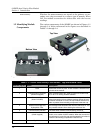
1-1 2150EX - Top and Bottom Views . . . . . . . . . . . . . . . . . . . . . . . . . . . . . . . . . . . . . . . 1-4
1-2 2150EX Connected to 2191EX- Top Right View . . . . . . . . . . . . . . . . . . . . . . . . . . . 1-5
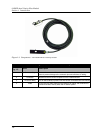
1-3 Components – AV2150EX Area Velocity Sensor . . . . . . . . . . . . . . . . . . . . . . . . . . 1-6
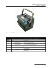
1-4 2191EX and 2196EX Battery Components . . . . . . . . . . . . . . . . . . . . . . . . . . . . . . . 1-7
1-5 2150EX Area Velocity Flow System Communication Connector Pins . . . . . . . . 1-11
2-1 Typical Round-pipe Installation Connected to a
Laptop Computer (Portable Installation, see section 2.4) . . . . . . . . . . . . . . . . . . . 2-5
2-2 Typical Round-pipe Installation Connected to a
2101 Field Wizard (Portable Installation, see section 2.4) . . . . . . . . . . . . . . . . . . 2-6
2-3 Typical Round-pipe Installation Connected to a
2194EX Module and Laptop
(Permanent Installation, see section 2.5) . . . . . . . . . . . . . . . . . . . . . . . . . . . . . . . . 2-7
2-4 Illustration of Battery Packs . . . . . . . . . . . . . . . . . . . . . . . . . . . . . . . . . . . . . . . . . . 2-9
2-5 Label Markings for LTC2191EX and SLA2191EX Battery Packs . . . . . . . . . . . . 2-9
2-6 Assembling a basic portable system . . . . . . . . . . . . . . . . . . . . . . . . . . . . . . . . . . . 2-11
2-7 Flowlink low-voltage warning . . . . . . . . . . . . . . . . . . . . . . . . . . . . . . . . . . . . . . . . 2-14
2-8 Location of 2196EX charging terminals . . . . . . . . . . . . . . . . . . . . . . . . . . . . . . . . 2-15
2-9 Detailed view of charging circuit board . . . . . . . . . . . . . . . . . . . . . . . . . . . . . . . . 2-16
2-10 2196EX battery module and labeling . . . . . . . . . . . . . . . . . . . . . . . . . . . . . . . . . 2-17
2-11 Amphenol connector pins for 12V adapter cable 69-2004-451 . . . . . . . . . . . . . 2-18
2-12 2194EX labels and cable connector . . . . . . . . . . . . . . . . . . . . . . . . . . . . . . . . . . 2-20
2-13 Network cable connector and wiring . . . . . . . . . . . . . . . . . . . . . . . . . . . . . . . . . 2-20
2-14 Network cable conduit fittings . . . . . . . . . . . . . . . . . . . . . . . . . . . . . . . . . . . . . . 2-21
2-15 Wiring the socket insert . . . . . . . . . . . . . . . . . . . . . . . . . . . . . . . . . . . . . . . . . . . 2-21
2-16 EX Network Cable for Connection to an Isolator Cable . . . . . . . . . . . . . . . . . . 2-22
2-17 RS232EX Isolator Cable for Connection to a Computer . . . . . . . . . . . . . . . . . . 2-23
2-18 RS485EX Isolator Cable for Connection to a 2100 Series Network Device . . . 2-24
2-19 Connecting the AV Sensor . . . . . . . . . . . . . . . . . . . . . . . . . . . . . . . . . . . . . . . . . 2-26
2-20 AV2150EX Sensor Cable Labels . . . . . . . . . . . . . . . . . . . . . . . . . . . . . . . . . . . . . 2-26
2-21 Sensor Installed on a Spring Ring . . . . . . . . . . . . . . . . . . . . . . . . . . . . . . . . . . . 2-29
2-22 Scissors Ring adjustment . . . . . . . . . . . . . . . . . . . . . . . . . . . . . . . . . . . . . . . . . . 2-32
3-1 Connection to a Laptop, Using Cables P/N 60-2004-336 and 60-2004-339 . . . . . . 3-1
3-2 Preferred Measurement Location . . . . . . . . . . . . . . . . . . . . . . . . . . . . . . . . . . . . . . 3-3
3-3 Zero Level Offset Measurement . . . . . . . . . . . . . . . . . . . . . . . . . . . . . . . . . . . . . . . 3-4
4-1 Configuration Example (Direct Connection Shown) . . . . . . . . . . . . . . . . . . . . . . . 4-3
5-1 Illustration of LTC2191EX Battery Packs . . . . . . . . . . . . . . . . . . . . . . . . . . . . . . . 5-3
5-2 SLA2191EX Battery Pack Voltage Chart . . . . . . . . . . . . . . . . . . . . . . . . . . . . . . . . 5-4
5-3 Lead-Acid SLA2191 EX Battery Packs and 8V2191SLA Charger . . . . . . . . . . . . 5-5
5-4 Inserting an SLA2191EX Battery Pack into the Charger . . . . . . . . . . . . . . . . . . . 5-6
5-5 Illustration of Battery Packs . . . . . . . . . . . . . . . . . . . . . . . . . . . . . . . . . . . . . . . . . . 5-7