


2150EX Area Velocity Flow Module
Section 4 Modbus Protocol
4-8
(1) A write to the Identify module register will cause the module to perform the identify operation which may be a steady
LED for a few seconds or a beep in the Field Wizard.
(2) Setting the Take Reading flag to 1 will cause the module to update the registers with current data readings. It will
be set to zero when the readings have all been updated. This may be used to initiate readings and poll for when
they are ready to be read. It may take up to 50 seconds to update all the readings, depending upon the flow con-
ditions. Setting the Take Reading flag to 2 causes an automatic, 15 second update of readings when a Modbus
master is polling the 2100.
(3) The Update Interval specifies an interval in seconds that the registers are automatically updated. It defaults to zero,
which indicates that no automatic updating will occur.
(4) The Active Flag (1-4) bit fields specify what fields/registers are active in the list. This provides support for a maxi-
mum of 64 fields. For example, if bit 0 of register 27 is set, the Level (registers 40,41) is active. If bit 1 of register
27 is set, then the Velocity (registers 55,56) is active. If bit 0 of register 28 is set, the Analog channel 7 (registers
265,266) is active.
(5)A non-zero status code indicates a measurement problem.
(6) Time is represented in a series of registers: Order is from lowest address to highest - Seconds (0-59), Minutes (0-59),
Hours (0-23), Days (1-31), Month (1-12) and Year (1977-2099).
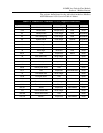
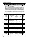
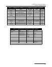
117 Volume 1 status code 16-bit integer Read
118-123 Volume 1 time record Time Read
130,131 Voltage 4-byte float Volts Read
132 Voltage status code 16-bit integer Read
133-138 Voltage time record Time Read
145,146 Temperature 4-byte float Degrees Celsius Read
147 Temperature status code 16-bit integer Read
148-153 Temperature time record Time Read
160,161 Internal Temp 4-byte float Degrees Celsius Read
162 Internal Temp status code 16-bit integer Read
163-168 Internal Temp time record Time Read
175,176 Analog channel 1 4-byte float 0-100 percent Read
177 Analog channel 1 status code 16-bit integer Read
178-183 Analog channel 1 time record Time Read
190,191 Analog channel 2 4-byte float 0-100 percent Read
192 Analog channel 2 status code 16-bit integer Read
193-198 Analog channel 2 time Record Time Read
205,206 Analog channel 3 4-byte float 0-100 percent Read
207 Analog channel 3 status code 16-bit integer Read
208-213 Analog channel 3 time record Time Read
220,221 Analog channel 4 4-byte float 0-100 percent Read
222 Analog channel 4 status code 16-bit integer Read
223-228 Analog channel 4 time record Time Read
235,236 Analog channel 5 4-byte float 0-100 percent Read
237 Analog channel 5 status code 16-bit integer Read
Table 4-2 Modbus ASCII Address 2-(N+1) Register Definitions (Continued)
Register Number(s) Name Data Type Units Read/Write