2150EX Area Velocity Flow Module
Section 4 Modbus Protocol
4-3
4.3 Configurations A variety of configurations can be made with Modbus, either
through direct connection or through a modem.
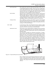
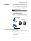
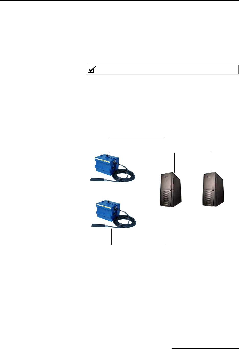
In the example shown in Figure 4-1, you are direct-connecting a
server PC to two individual 2150s through Modbus, using the
COM ports on the OPC Server, which are directly connected to
the remote 2150s.
Connection to the module is made through the RS-232 communi-
cation port on the top of the module.
Note
For low power operation, we recommend connecting the mod-
ule(s) to the computer using the straight-through cable (Isco
part number 60-5314-529), which consumes less power,
instead of our standard interrogation cable.
In Figure 4-1, the OPC Server PC must have two COM ports.
Modbus requires one COM port each, for direct connection of
each 2150.
Figure 4-1 Configuration Example (Direct Connection Shown)
The operation sequence for the example above can be summa-
rized in the following steps:
2150:
1. 2150s take readings from probes.
2. 2150s store readings (level, velocity, flow rate, etc.) in their
specified registers.
Process Control:
3. The user requests data through Process Control.
4. Process Control asks the OPC server to gather informa-
tion.
2150
2150
OPC
Server
Process
Control
COM
port 1
COM
port 2


