


2150EX Area Velocity Flow Module
Section 2 Preparation and Installation
2-23
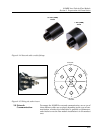
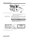
CAUTION
Caps PUSH ON and PULL OFF. Do not rotate the caps to
remove them from the connectors.
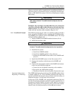
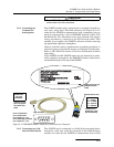
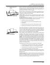
2.6.2 Connecting to a
Computer for
Interrogation
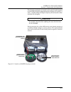
The 2150EX module can be connected to a computer located in a
safe area, using Isco’s Flowlink software (see Figure 2-1). In
order for the 2150EX to communicate with a computer, the two
must be connected by an Isco RS232EX Isolator Cable (P/N
60-2004-339). The hazardous area end, labeled with proper
entity parameters, connects to the EX Network cable. This
enables you to update the 2150EX’s software without entering
the potentially explosive atmosphere.
Observe intrinsic safety requirements regarding proximity to
external sources of potential electric or magnetic interference.
Refer to IEC 10079-14 section 12.2.2.5 on installation of cables
and wiring.
If the 2150EX and AV 2150EX sensor are not located in a poten-
tially explosive atmosphere, the RS232EX isolator cable can be
connected directly to the top of the 2150EX.
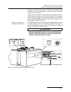
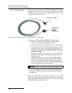
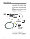
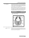
Figure 2-17 RS232EX Isolator Cable for Connection to a Computer
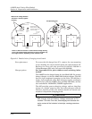
2.6.3 Connecting to a 2100
Series Network Device
The 2150EX can be connected to a 2100 Series network device
located in a safe area (with the exception of the 2102 Wireless
module). In order for the 2150EX to communicate with a 2100
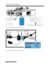
12345
6
7
89
RATED INPUT
25V 1/2A
EIA-RS232
connects to com-
puter using maxi-
mum 250V (Um =
250V)
Hazardous Area End
Ui = 9.282V
I i = 4.000A
Pi = 4.000W
Ci = 2.827uF
Li = 0.000uH
connects to an
EX Network Cable
(P/N 60-2004-336)
Label marking for the
RS232EX Isolator
Cable
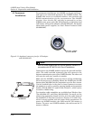
Pin 2 Transmit Data
Pin 3 Receive Data
Pin 4 Requires 3 - 15V
Pin 5 Power/Signal Ground
Pin 7 Requires 3 - 15V
Safe Area End