


2150EX Area Velocity Flow Module
Section 2 Preparation and Installation
2-22
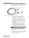
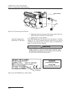
2.6.1 EX Network Cable The EX Network cable (2m P/N 60-2004-335, 8m P/N
60-2004-336) connects to the top of the 2150EX stack and
extends to the interface of the safe and hazardous areas, where
the actual isolation is located.
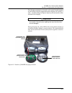
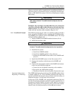
Figure 2-16 EX Network Cable for Connection to an Isolator Cable
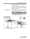
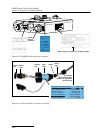
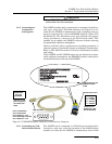
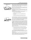
To connect the EX Network and RS232EX isolator cables:
1. Remove the protective cap from the communication
connector on the top of the 2150EX module.
2. Store the protective cap in the holder next to the connector.
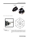
3. Push the 6-pin end of the EX Network cable onto the com-
munication connector on the top of the 2150EX module.
Use care, so you do not misalign the pins and cause
any short circuits.
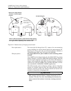
4. Route the cable as shown in Figure 2-1, so the other end of
the EX Network cable is at the interface of the safe and
hazardous areas.
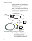
5. Attach the hazardous area end of the RS232EX isolator
cable to the EX Network cable coming from the 2150EX.
Use care, so you do not misalign the pins and cause any
short circuits! Attach the other end of the RS232EX cable
to the appropriate port on your computer.
Note
You can safely connect and disconnect the RS232EX cable
from the EX Network cable without removing the 2150EX mod-
ule or the EX Network cable from the potentially explosive
atmosphere.
When the communication connector is not in use, it should
always be capped to prevent corrosion and improve communica-
tions. When the communication connector is in use, store the cap
on the holder next to the connector.
Connects to a 2150EX
Connects to an
RS232EX or
RS485EX
Isolator Cable