


2150EX Area Velocity Flow Module
Section 2 Preparation and Installation
2-11
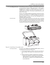
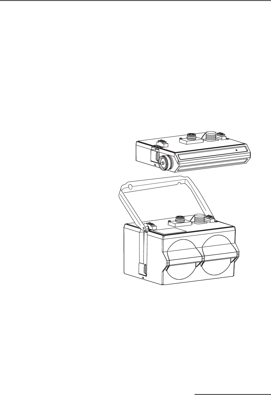
2.4.5 Assembling the System The 2100 Series System is modular; you build the system by con-
necting modules together. The instructions in this section
describe how to connect a 2150EX module to a 2191EX or
2196EX battery module in its most basic configuration — by
stacking the two modules. The battery module must be at the
bottom of the stack.
You can use multiple modules in a stack to increase the site’s
functions. A maximum of two 2150EX modules may be powered
by one battery module, to avoid overloading the batteries.
However, within a stack, you can have multiple sets of
2150EX/2191EX combinations.
Connection options Keep in mind that stacking is not the only way to connect
modules. The modules may be placed in remote locations and still
operate as a single site. If you would like to use remote modules
for your application, please consult with the factory or your rep-
resentative to realize the full potential of your system.
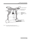
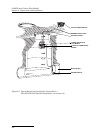
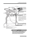
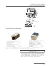
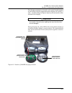
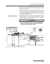
Figure 2-6 Assembling a basic portable system
Connecting the Modules To connect the 2150EX and 2191EX/2196EX modules, refer to
the following instructions and Figure 2-6.
1. On the top of the battery module, remove the cap and stow
it on the holder. This exposes the communication connec-
tor.
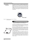
2. Prepare the battery module’s communication connector:
a. Inspect the connector. It should be clean and dry. Dam-
aged O-rings must be replaced. Spare O-rings (P/N
202-1006-69) are supplied in the 2191EX maintenance
kit (60-2009-332).