


2150EX Area Velocity Flow Module
Section 2 Preparation and Installation
2-16
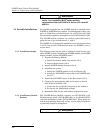
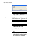
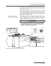
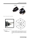
Figure 2-9 Detailed view of charging circuit board
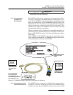
Fuse replacement To access the 2A charge fuse (F1), remove the two mounting
screws holding the circuit board inside the compartment lid.
Replace the fuse with the specified Littlefuse 216002 or
Cooper/Bussman S501 only (Isco part #411-9922-60).
Charger options See Appendix B for part numbers and ordering infor-
mation.
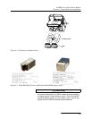
The 2196EX can be charged using the Isco Model 965 five-station
battery charger, or the Isco Model 963 desktop charger. The 965
has five 2-pin amphenol connectors on the front. The 963 has a
single, 2-pin amphenol cable. Both chargers require an adaptor
cable for use with the 2196EX (Isco part #60-1394-023), and are
user-switched for 120/240VAC, 50/60Hz applications.
The 965 provides greater charging voltage, and can therefore
charge to a higher capacity than the other chargers offered.
However, because of this, the module should not remain con-
nected to it beyond the charging period.
CAUTION
The module should not remain connected to the Isco Model
965 charger after the Battery Voltage measured at TP1
reaches 13.8 volts. Over time, overcharging can decrease the
water content of the batteries’ electrolyte, causing premature
aging.
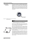
H19
BATTERY VOLTS (TP1)
NEVER
CHARGE IN
POTENTIALLY
EXPLOSIVE ENVIRONMENT
(-) NEGATIVE (+) POSITIVE
FUSED
INPUT
VOLTAGE
(LED)
MAXIMUM 50 CELSIUS
AMBIENT DURING CHARGE
MAXIMUM CHARGER RATING
20 VOLTS 2 AMPERES
Um = 250V
Un = 20V
Front
Back
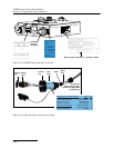
Measure the voltage between
Test Point 1 and H5 (negative
terminal).
2A replaceable fuse
There is a 60K ohm resistor in series with the voltage sensing
circuit. The voltage reading measured on the circuit board may
have slight variance, depending on the voltmeter used.