


2150EX Area Velocity Flow Module
Section 3 Programming
3-7
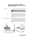
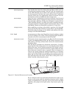
If the selected flow conversion requires channel dimensions,
actual channel measurements should be taken. Channel measure-
ments are preferred over nominal values. Significant errors may
be introduced if your measurements are inaccurate. The example
below illustrates the importance of accurate measurements.
Refer to the information in Section 3.3.1 to determine where to
measure the channel dimensions.
3.3.5 Silt Level Silting in the flow stream will alter your channel dimensions,
affecting the flow rate conversion. To compensate for a buildup of
silt, a Silt Level value can be entered on the Flow Rate mea-
surement tab in Flowlink. Silt level compensation is only
available when using Area Velocity flow conversion.
3.3.6 Data Storage Rates The data storage function of a 2150EX can record level, velocity,
flow rate, total flow, and input voltage readings. The interval at
which the 2150EX stores the readings is called the Data Storage
Rate. The 2150EX is shipped with default storage rates of 15
minutes for the level, velocity, and flow rate, and 1 hour for total
flow and input voltage readings.
You can modify the data storage rates to log readings at a faster
or slower rate. Keep in mind that although the 2150EX can store
data as fast as 1 reading every 15 seconds, faster storage rates
will shorten battery life, increase memory usage, and lengthen
Retrieve Data (interrogation) times.
You can also create conditional data storage rates. The 2150EX
can log data at a secondary rate when user-defined conditions
have been met. For example, a 2150EX can store level readings
at a primary rate of 15 minutes, and a secondary rate of 1 minute
when the level reading is greater than or equal to 1 foot. Sec-
ondary rates allow you to collect detailed data when defined
events of interest occur, while reducing power and memory con-
sumption when detailed readings are not needed.
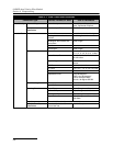
To modify the Data Storage Rates, first click on the Set Up Data
Storage… button on a measurement tab. Then enter the Primary
and Secondary Rate settings on the Data Storage Setup window.
Repeat this for each measurement type.
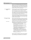
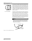
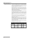
Nominal Pipe Diameter: 10 inches
Actual Pipe Diameter: 10.25 inches
Level Measured Near Outfall: 2.75 inches
Correct Level Measurement: 3 inches
During programming, you enter 10 inches for the round pipe
diameter - from the pipe manufacturer’s specification. You
also enter the 2.75 inch level measurement taken behind the
sensor near an outfall. Although each setting has only a 0.25
inch error, the cumulative flow measurement error may
exceed 14%!
Example: