


2150EX Area Velocity Flow Module
Section 1 Introduction
1-6
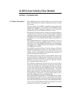
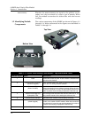
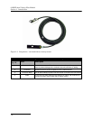
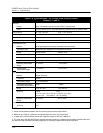
Figure 1-3 Components – AV2150EX Area Velocity Sensor
1
2
3
4
Table 1-3 Components – AV2150EX Area Velocity Sensor
Item No.
Fig. 1-3
Name Description
1 Connector Cap Protects the connector. When the connector is not in use, this cap must be in
place to prevent damage to the connector pins and reference air tubing.
2 Connector Attaches to the AV Sensor receptacle on the 2150EX Module.
3 AV Sensor Body The AV Sensor Body is placed in the flow stream to measure level and velocity.
4 Cable 10.0 m (32.8 ft) cable containing the reference air tubing and conductors to
transfer level data, velocity data, and AV Sensor power.