


11. PLC Help Function
11.6 External Machine Coordinate System Compensation
- 398 -
11.6 External Machine Coordinate System Compensation
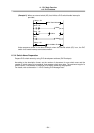
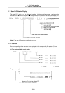
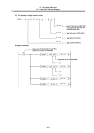
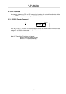
External machine coordinate system compensation is executed by setting compensation data
(absolute amount) in the PLC file register (R) for each axis.
Thus, the compensation timing is when PLC rewrites file register (R) compensation data. Necessary
condition, timing, etc., are set by user PLC.
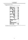
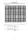
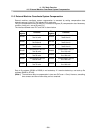
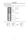
The interface between user PLC and CNC is shown below.
File
register
Contents
File
register
Contents
R2300
Compensation data for
the 1st axis
R2650
Compensation data for
the 8 th axis
R2350
Compensation data for
the 2nd axis
R2700
Compensation data for
the 9 th axis
R2400
Compensation data for
the 3rd axis
R2750
Compensation data for
the 9 th axis
R2450
Compensation data for
the 4th axis
R2800
Compensation data for
the 11th axis
R2500
Compensation data for
the 5th axis
R2850
Compensation data for
the 12th axis
R2550
Compensation data for
the 6th axis
R2900
Compensation data for
the 13th axis
R2600
Compensation data for
the 7th axis
R2950
Compensation data for
the 14th axis
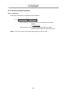
Data in file registers (R2300 to R2950) is not backed up. If it must be backed up, use back-up file
registers (R6400 to R7199).
(Note 1) The maximum delay to compensation is (one user PLC scan + 15ms). However, smoothing
time constant and servo follow delay are not contained.