


11. PLC Help Function
11.3 PLC Switches
- 385 -
11.3 PLC Switches
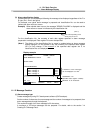
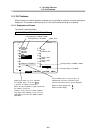
Similar function to machine operation switches can be provided by using the controller setting and
display unit. The number of switch points is 32. The switch names can be given as desired.
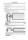
11.3.1 Explanation of Screen
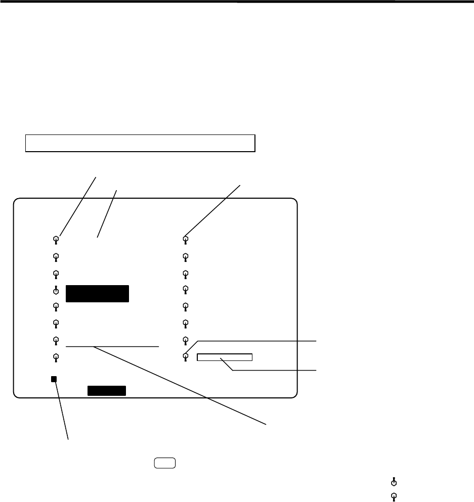
The screen is explained below.
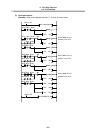
PARAMETER SCREEN PLC SWITCH (MENU)
PLC-SW
OPTIONAL
STOP
[PLC-SWITCH]
#
1
2
3
4
5
6
7 MACRO INTERRUPT
8
9
10
11
12
13
14
15
16
PARAM 6. 1/2
LOC-VAR MENU
#( )
Corresponding to R38/bitF, SM95
Corresponding to R138/bitF
Switch mark
Corresponding to R138/bit0
Corresponding to R38/bit0, SM80
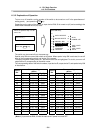
For the switch name, a string of up to 14
alphanumeric and kana characters (kanji
requires 2-character space) can be displayed.
Switch on state display part :
Switch off state display
Setting part switch on, off is indicated.
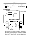
For example, when 1 is set and
is pressed, #1 switch is turned on.
When the same operation is again performed,
the switch is turned off.
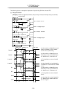
However, on/off control of certain switches
may trigger other switches to turn on or off
(depending on the user PLC SM80 to SM111
operations).
INPUT
AUTO
RESTART
BLOCK
DELETE
MANUAL
ABS
AUTO
POWER OFF
CHIP CNVR
MANL
CHIP CNVR
AUTO
COM-VAR
: