


6. Explanation of Commands
6.2 Command Formats
- 96 -
6.2 Command Formats
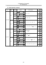
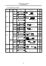
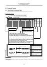
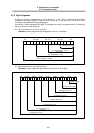
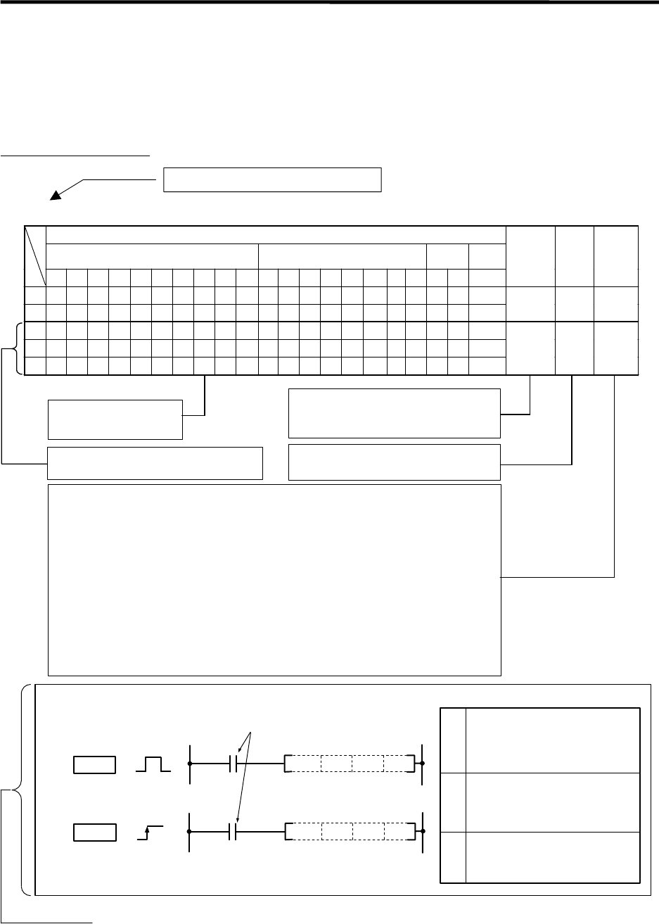
6.2.1 How to Read the Command Table
The basic command and function command explanations are as follow.
Example of D+ command
○D+,D+P
……
BIN 32-bit addition
Usable device
Bit device Word device
Con-s
tant
Poin-
ter
X Y M L F B SB T SM V T C D R W SW Z SD K H P
Digit
desig-
nation
Index
No. of
steps
S
{ { { { { { {
{
{ { { { { { { { { {
D
{ { { { { {
{
{ { { { { { { {
{ {
3/4
S1
{ { { { { { {
{
{ { { { { { { { { {
S2
{ { { { { { {
{
{ { { { { { { { { {
D
{ { { { { {
{
{ { { { { { { {
{ {
4/5
The command signal is indicated.
The commands that can use
an index (Z0 to Z13) are circled.
Expressed with T.
Same applies for C.
The devices that can be used with
the D+ command are circled.
A circle is indicated if digit
designation of the bit device is
possible.
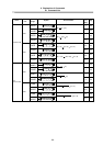
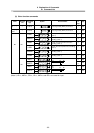
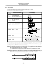
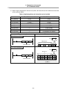
The No. of steps of the D+ command is indicated.
This is a No. of steps required for the store in the controller.
In programming with MELSEC PLC development tool (GX Developer), the
displayed No. of steps may be different from this No. of steps.
Description such as “4/5” indicates that the No. of steps is different
depending on the designation device or the type of the command. For the
32-bit command, two steps are required for the constant. In the example for
the D+ command, if S2 is the word device, the No. of steps will be 4 steps,
and if S2 is the constant, the No. of steps will be 5 steps.
The command executed only at the leading edge (***P command) uses 6
steps bigger than the command executed when ON(***command).
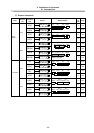
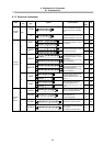
Setting data
S2
S1
D
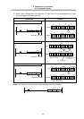
The D+ command circuit display format is indicated.
Addition command
D+P S2S1 D
D+
D+P
D+
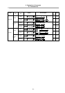
S2
S1 D
Addition data or head No. of
device where addition data is
stored.
Addition data or head No. of
device where addition data is
stored.
Head No. of device to store
addition results.
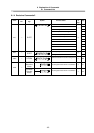
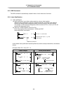
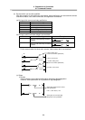
The functions, execution conditions and program examples of each command are explained on the
following pages.