


6. Explanation of Commands
6.2 Command Formats
- 97 -
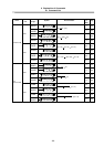
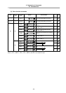
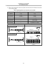
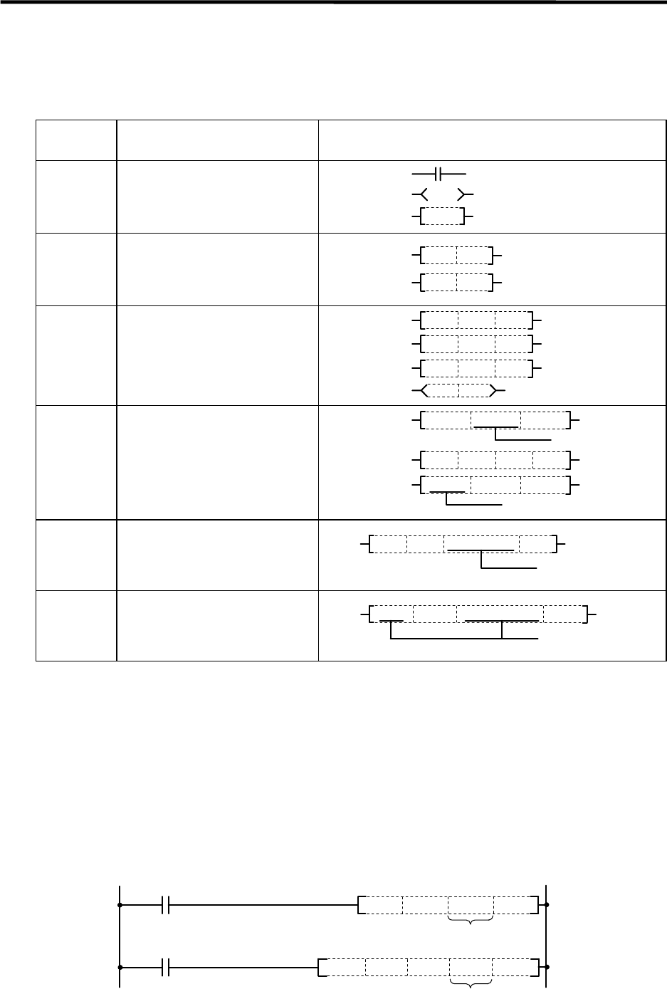
6.2.2 No. of Steps
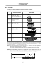
The basic No. of steps in the sequence command includes step 1 to step 6.
Main examples of each step are shown below.
Basic No.
of steps
Command (mnemonic) Circuit display
Step 1
LD, ANI, ANB, ORB,
STC, CLC, FEND, RET, P**
FEND
Step 2
INC, DEC, PLS, PLF,
CJ, CALL
INC
D10
CALL
P20
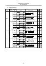
Step 3
MOV, =, BCD, OUT, T
D0 D1
BCD
D0
D1
K100
D100
T1 K1
MOV
=
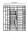
Step 4
DMOV, +, -, XCH
DMOV K12345
D0
+
K100
D0 D1
XCH D0 D10
2 steps worth
2 steps worth
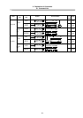
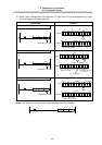
Step 5
D+, D-
D+
H12345678
D0 D10
2 steps worth
Step 6
D*, D/
D*
K123456
D0
D10
2 steps worth
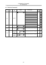
As shown above, the command code, source and destination in basic No. of steps for the command
are equivalent to one step each. Only a part of commands, the 32-bit command constant K, H, a part
of command code B, SB, V, T or C device uses two steps.
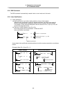
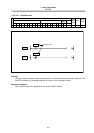
(Note1) The command executed only at the leading edge (***P command) uses 6 steps bigger than
the command executed when ON (*** command).
For example, the MOV command uses 3 steps, and the MOVP command uses 9 steps.
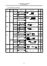
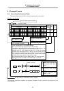
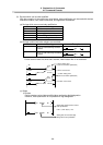
(Note2) If the constant value in the DMOV or D* command, etc., is small, a display in which there is a
space equivalent to one step will occur between the source (S) and destination (D) or
between the source (S2) and destination (D). (Section marked with * in diagram.)
DMOV K12 D0
D*
K50D0
D4
(S)
(D)
(S1)
(S2)
(D)
*
*