


11. PLC Help Function
11.3 PLC Switches
- 387 -
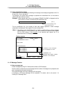
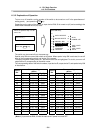
The table below shows the message displayed during operation on the PLC switch screen.
No. Message Explanation Remedy
E01
SETTING
ERROR
A number outside the allowable
setting range from 1 to 32 is specified
in # ( ).
Specify a valid number within the
range.
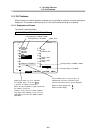
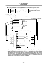
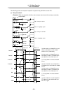
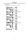
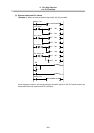
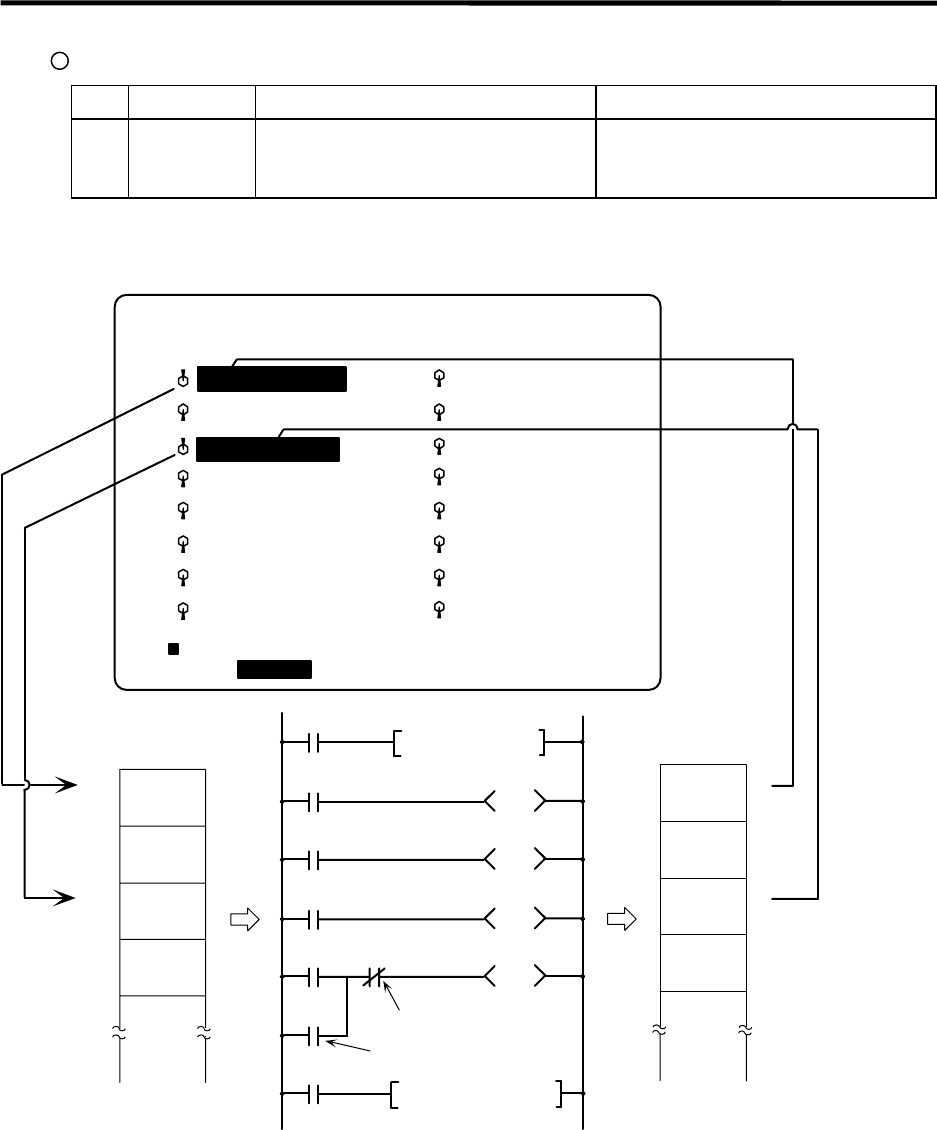
11.3.3 Signal Processing
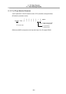
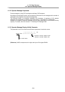
4
The characters are highlighted.
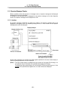
[PLC-SWITCH]
#
1
2
3
5
6
7 MACRO INTERRUPT
8
9
10
11
12
13
14
15
16
PARAM 6. 1/2
#( )
AUTO RESTART
BLOCK DELETE
MANUAL ABS
OPTIONAL STOP
AUTO
POWER OFF
CHIP CNVR
MANL
CHIP CNVR
AUTO
LOC-VAR MENUCOM-VAR
M100
M0
M101M1
M3 X9
MOV R38 K4M0
M2
M102
MOV K4M100 R138
Always ON
X8
Always ON
Condition for validity
M103
Input:R38
Output:R138
1
0
1
0
1
0
1
0
External switch
PLC-SW
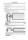
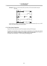
· When setting is done on the PLC switch screen, the input device R38, R39 corresponding to the
specified switch number is turned on or off to switch over the switch state.
· When special relay SM is turned on from the user PLC, its corresponding input device R38, R39
and the switch state are reversed. Special relay SM is reset immediately after the CNC reverses
the input device R38, R39 and the switch state. It is turned on by one pulse (scan) only also in the
user PLC. In either case, when output device R138, R139 is set to on based on the input device
R38, R39 state, the corresponding switch name is highlighted.