


4
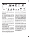
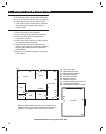
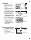
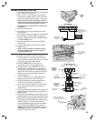
EXAMPLE SYSTEM
✦ The example shows a typical DUAL 824 system.
✦ Any or all of the accessories shown can be used.
✦ A total of 24 sensors can be used with each
Control Panel. Each wireless sensor, hardwired
loop, and wireless keypad used occupies a
sensor location.
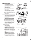
DESIGN THE INSTALLATION
1. Draw a fl oor plan for the installation.
2. Consider the security needs of the premises.
3. Determine which doors and windows are
vulnerable to intrusion.
4. Figure which interior areas an intruder might go
to if unlawful entrance is gained.
5. Indicate locations for door/window sensors,
interior motion detectors, wireless and hardwired
keypads, glass break detectors and external
siren speakers.
6. Decide on a centralized location for the security
Control Panel.
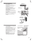
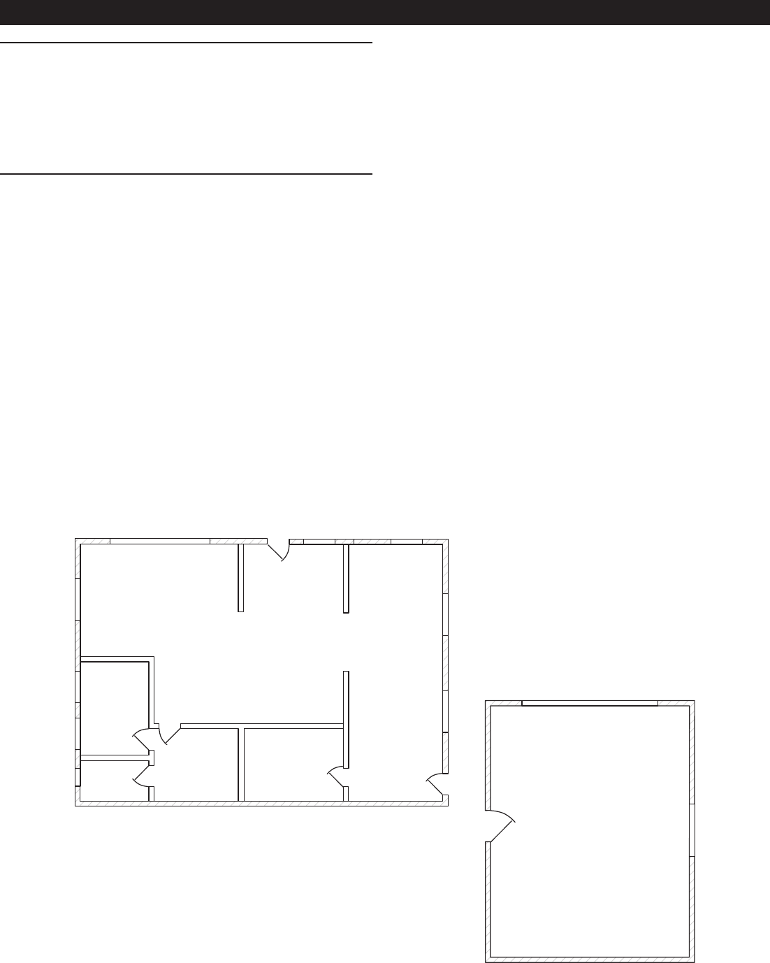
2. SECURITY SYSTEM FLOOR PLAN
CP
S
GARAGE
MS
S
MD
ES
HK
S
S
MD
MS
S
S
CP - CONTROL PANEL
HK - HARDWIRED KEYPAD
S - DOOR/WINDOW SENSOR
WK - WIRELESS KEYPAD
MD - MOTION DETECTOR
ES - EXTERNAL SIREN
SD - SMOKE DETECTOR
CO - CARBON MONOXIDE DETECTOR
GB - GLASS BREAK SENSOR
MS - HARDWIRED MAGNETIC SWITCH
LIVING
DINING
KITCHEN
ENTRY
BED
BATH
DEN
GB
SD
GB
BED
NOTE: IN NEW CONSTRUCTION, NFPA 72 REQUIRES A
SMOKE DETECTOR LOCATED INSIDE EACH BEDROOM
AS WELL AS A SMOKE DETECTOR ON EACH LEVEL.
MS
WK
HK
S
S
S
CO
Example Residential Security System Floor Plan