


10
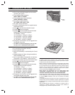
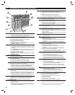
HARDWIRED LOOP WIRING
✦ The DUAL 824 supports up to eight normally
open/closed hardwired loops each with 2.2K
end-of-line resistor supervision.
✦ Each hardwired loop that is wired and
programmed uses one sensor location.
✦ Each hardwired loop can be programmed to any
sensor number.
✦ Each hardwired loop can be programmed as any
sensor type, including arm/disarm toggle.
✦ Four COM terminals are shared as loop returns
for the eight loops.
✦ Each hardwired loop has a 400 millisecond
response time.
✎ NOTE: For UL installations, use UL Listed cable for
all hardwired loop wiring.
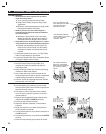
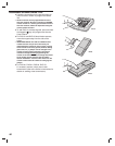
1. Route wiring from the Control Panel to each
hardwired switch contact, sensor, or device.
Route the wires through the wiring slot or
through a knockout for conduit wiring.
✎ NOTE: Maximum recommended hardwired loop
length is 500 feet (250' out, and 250' back) for each
loop. Maximum loop resistance (excluding the EOL
resistor) is 100 ohms.
2. Connect the loop wires to LOOP # and COM
terminals. For powered devices connect power
wires to +12 VDC and any COM terminal.
3. On the sensor end, connect each normally
closed sensor in series with the loop wires.
Connect each normally open sensor in parallel
with the loop wires. See wiring fi gure.
4. After the last sensor on the loop, connect a 2.2K
end-of-line resistor across the loop.
✎ NOTE: Before the hardwired loops will function,
they will need to be programmed. This will be
covered in the Basic Control Panel Programming
section of this manual.
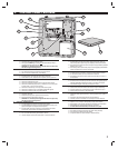
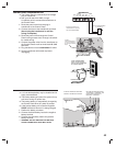
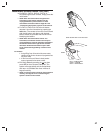
ARM/DISARM KEY STATION WIRING
✦ Any of the hardwired loops can be used with a
momentary keyswitch to arm and disarm the
system.
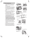
1. Connect the loop as shown to the keyswitch and
end-of-line resistor.
2. Connect an LED indicator from the switch plate
to the H/A- and H/A+ terminals.
3. When programming the system, set the loop
sensor function to “Type 9, Arm/Disarm Toggle”
and set the Automation output to “Active while
Armed”.
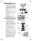
RUN LOOP WIRING
BETWEEN THE CONTROL
PANEL AND THE REMOTE
HARDWIRED SENSORS
RUN 4-CONDUCTOR WIRE
TO POWERED DEVICES
RUN 2-CONDUCTOR WIRE
TO DEVICES NOT POWERED
FROM THE CONTROL PANEL
4-CONDUCTOR
FOR HARDWIRED
INFRAREDS
2-CONDUCTOR
FOR MAGNETIC
CONTACTS
LOOP
1
COM LOOP
2
LOOP
3
COM LOOP
4
LOOP
8
H/A
-
H/A
+
RLY
COM
RLY
N/C
RLY
N/O
COM
2.2K END-OF-LINE
RESISTOR FOR
EACH LOOP USED
NORMALLY CLOSED
SWITCHES (CONTACTS)
NORMALLY OPEN
SWITCHES (CONTACTS)
USE +12 VDC AND
ANY COM TERMINAL
TO POWER EXTERNAL
DEVICES (1 AMP MAX.)
MAIN TERMINAL BLOCK
+12
VDC
CONNECT EACH HARDWIRED
INPUT TO A LOOP AND COM
TERMINAL
FOR POWERED DEVICES, WIRE
POWER LEADS TO +12 VDC
AND ANY COMMON TERMINAL
(OBSERVE POLARITY)
LOOP
1
COM LOOP
2
LOOP
3
COM LOOP
4
LOOP
8
H/A
-
H/A
+
RLY
COM
RLY
N/C
RLY
N/O
COM
NORMALLY CLOSED,
SPRING RETURN, KEYSWITCH
470 OHM
KEYSTATION
2.2K OHM
LED
PROGRAM AUTOMATION
OUTPUT FOR "ACTIVE
WHILE ARMED"
LED WILL LIGHT
WHEN SYSTEM
IS ARMED
PROGRAM LOOP FOR
ARM/DISARM TOGGLE
(SENSOR TYPE 9)
MAIN TERMINAL BLOCK