


8
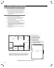
SYSTEM LOCATION
✎ NOTE: Wireless sensor signals must be able to
reach the Control Panel.
✔ Try to centrally locate the Control Panel.
✔ Keep Control Panel away from large metal
appliances.
✔ Maximum recommended sensor range is 400
feet (system tested at 1000 feet).
✎ NOTE: If you don't use the wireless keypad, a
hardwired keypad should be easily accessible to
the usual entrance.
✔ When the Control Panel is set in the Away
Mode, the user has 30 seconds to switch to
Off Mode before the burglary siren sounds.
✎ NOTE: Make sure a hardwired keypad is in a place
where the alarm can be heard during the night hours.
✔ Optional remote external sirens (up to 150
feet from the Control Panel) can be used to
make alarms louder and remote the sound
location.
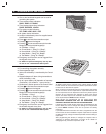
1. Locate the Control Panel near a 115 VAC outlet
that's not controlled by a light switch.
2. Locate the Control Panel near a telephone outlet
(if using the digital communicator).
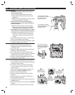
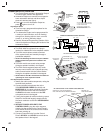
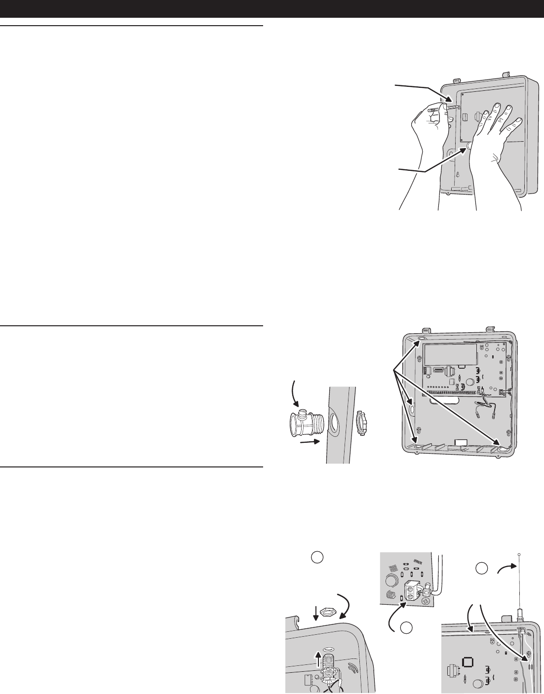
WALL MOUNTING
1. Use the Control Panel's case bottom as a
template and mark the locations for the four
mounting screws.
2. Mark the wiring access slot if the wiring is being
routed from behind the cabinet.
3. Use a hole saw to cut out the location for the
wiring access slot (if used) or punch out selected
cabinet wiring knockouts for conduit wiring.
4. Use four screws and appropriate screw anchors
to mount the unit to the wall.
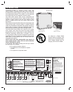
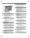
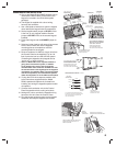
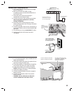
EXTERNAL ANTENNA
✦ Linear's Model LA-P antenna kit can be used
with the DUAL 824P Control Panel to replace the
standard internal antenna.
✦ The antenna can be mounted on the cabinet,
or the kit can be used to connect to co-ax for a
remote antenna.
1. Remove the two standard white antenna wires
attached to the ANT and SHIELD terminals.
2. Punch out the antenna knockout.
3. Mount the antenna connector in the antenna
knockout.
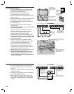
4. Route the antenna co-ax down to the Control
Panel's antenna connector.
5. Connect the antenna's co-ax center conductor to
the ANT terminal.
6. Connect the antenna's co-ax shield to the SHIELD
terminal.
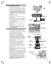
7. Route the two antenna ground wires as shown.
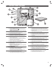
6. CONTROL PANEL INSTALLATION
USE THE CASE BOTTOM
AS A TEMPLATE TO MARK
THE FOUR KEYHOLE
MOUNTING HOLES
FOR RECESSED WIRING,
MARK WIRING SLOT, THEN
CUT OUT HOLE WITH
DRYWALL SAW
FOR CONDIUT WIRING,
PUNCH OUT REQUIRED
KNOCKOUTS AND INSTALL
3/4" CONDUIT HUBS IN
HOLES
PUNCH OUT ANTENNA
KNOCKOUT AND
INSTALL LA-P ANTENNA
CONNECTOR INTO HOLE
1
2
CONNECT CO-AX
SHIELD TO SHIELD
TERMINAL AND CO-AX
CENTER CONDUCTOR
TO ANT TERMINAL
3
INSTALL THE WHIP
ANTENNA AND ROUTE
THE TWO GROUND
WIRES AS SHOWN