


13
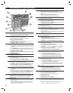
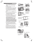
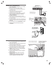
CONTROL PANEL POWER CONNECTION
✦ The Control Panel is powered by a low voltage
plug-in transformer.
✦ Use up to 25 feet of 20 AWG or larger
2-conductor wire to connect the transformer to
the Control Panel.
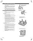
1. Route the power wires from the plug-in
transformer to the Control Panel.
2. Connect the wires to the transformer terminals
(do not plug the transformer in until the
wiring is complete).
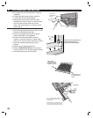
3. Route the power wires through the Control
Panel's wiring access slot or through a knockout
for conduit wiring.
4. Connect the power wires from the transformer to
the Control Panel's main terminal block AC & AC
terminals.
5. Plug transformer into an unswitched AC outlet.
6. Secure transformer with screw to prevent
unplugging.
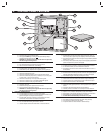
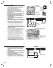
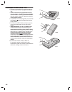
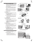
BACKUP BATTERY INSTALLATION
✦ A 12-volt backup battery may be installed and is
highly recommended.
✦ The backup battery will power the system for up
to 6 hours during AC power loss.
✦ The backup battery is automatically charged by
the Control Panel when AC power is present.
✦ A low backup battery will cause the keypad's
POWER indicator to fl ash as it is being charged.
1. Position the battery as shown.
2. Connect the black battery lead to the negative
battery terminal.
3. Connect the red battery lead to the positive
battery terminal.
✎ WARNING: DO NOT REVERSE THE BATTERY
LEADS! THE BATTERY FUSE WILL BLOW.
KPD
CLK
KPD
DAT
KPD
SPK +
KPD
SPK-
AC AC
KPD
-
MAIN TERMINAL BLOCK
XFRMRKEYPAD
PLUG-IN TRANSFORMER
16 VAC, 28 VA
BE SURE TO SELECT AN
UN-SWITCHED AC OUTLET
FOR THE TRANSFORMER
CONNECT
TRANSFORMER WIRES
TO THE AC TERMINALS
ON THE MAIN TERMINAL
BLOCK
TRANSFORMER
115 VAC
OUTLET
PLUG TRANSFORMER
INTO 115 VAC OUTLET
THAT IS NOT CONTROLED
BY A LIGHT SWITCH
SCREW
AFTER ALL WIRING IS COMPLETE,
CONNECT THE BACKUP BATTERY
BE SURE RED WIRE ATTACHES
TO POSITIVE (+) TERMINAL, AND
BLACK WIRE ATTACHES TO
NEGATIVE (-) TERMINAL