


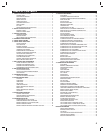
9
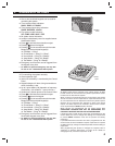
HARDWIRED KEYPAD INSTALLATION
✦ One or two Model DUAL 824KP keypads can be
used with the DUAL 824P Control Panel (one
keypad is included in the DUAL 824 system
package).
✦ The keypad is supplied with a short wiring
harness and connector.
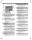
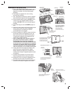
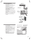
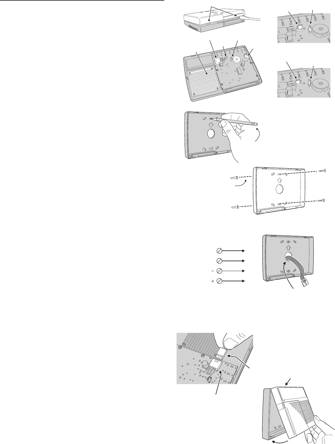
1. Use a fl at blade screwdriver to open the keypad
case. Identify the keypad internal components.
2. Set the keypad select jumper to KEYPAD 1 if this
is the fi rst, or only, keypad installed. Set the
jumper to KEYPAD 2 if this is the second keypad
installed.
3. For a silent keypad, set the SOUNDER jumper to
OFF.
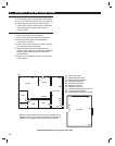
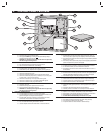
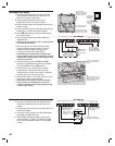
4. Select an indoor location with easy wiring access
to the Control Panel and use the keypad's
mounting plate as a template to mark the
mounting holes for the keypad.
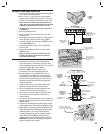
5. Route 4-conductor 22 AWG (or larger) wire from
the Control Panel to the keypad(s). Up to 100
feet of wire total can be used with this system.
If installing two keypads, each keypad can be
“home-run” or “daisy-chained”.
✎ Note: If a Model VB-2 voice response module is
going to be used with the system, in addition
to the keypad’s four wires, route 2-conductor
shielded cable and 2-conductor 22 AWG wire from
the Control Panel to the keypad(s) for the keypad’s
microphone and speaker. When using two keypads
and two microphones, each shielded microphone
cable must be home run to the VB-2 terminal block.
6. If using the VB-2 voice response module, refer
to the instructions supplied with the Model
RSM-2 speaker/microphone kit for details on
installing and wiring the keypad’s speaker and/or
microphone.
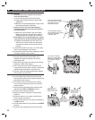
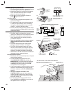
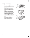
7. Connect the 4-conductor wire to the Control
Panel's keypad terminals, noting wire colors.
8. Noting wire colors, connect the keypad's wiring
harness to the wire from the Control Panel.
9. Plug the keypad wiring harness into the keypad
connector and snap the keypad case closed.
DEFAULT JUMPER POSITIONS
ALTERNATE JUMPER POSITIONS
TWIST SCREWDRIVER
IN SLOTS TO OPEN
THE KEYPAD CASE
RSM-2 KIT
SPEAKER
LOCATION
KEYPAD
CONNECTOR
SOUNDER
JUMPER
(ON OR OFF)
KEYPAD
SELECT
JUMPER
(KPD1 OR KPD2)
RSM-2 KIT
MICROPHONE
LOCATION
SOUNDER JUMPER
SET TO "ON"
KEYPAD SELECT
JUMPER SET
TO "KEYPAD 1"
SOUNDER JUMPER
CAN BE SET TO "OFF"
SET KEYPAD SELECT
JUMPER TO "KEYPAD 2"
IF THIS IS THE 2ND KEYPAD
COMPONENT
LOCATIONS
NOTE: MAXIMUM RECOMMENDED
WIRE RUN IS 100 FEET COMBINED
TOTAL FOR ALL KEYPADS
MOUNT KEYPAD INDOORS
AT A CONVENIENT HEIGHT
AND LOCATION FOR THE USERS
USE THE MOUNTING PLATE
AS A TEMPLATE TO MARK
SCREW LOCATIONS
USE SCREWS AND ANCHORS
OR APPROPRIATE FASTENERS
TO AFFIX MOUNTING PLATE
THE MOUNTING PLATE IS ALSO
DESIGNED TO BE ATTACHED
TO A SINGLE-GANG OUTLET BOX
DUAL 824P
CONTROL PANEL
TO
DUAL 824KP
KEYPAD
IF THE RSM-2 SPEAKER/MICROPHONE KIT IS
GOING TO BE USED, RUN AN ADDITIONAL PAIR
FOR THE SPEAKER AND A SHIELDED PAIR
FOR THE MICROPHONE
ROUTE WIRING
CONNECTOR THROUGH
MOUNTING PLATE HOLE
KPD DAT
KPD CLK
KPD
KPD
WHITE
ORANGE
BLACK
RED
ROUTE 4-CONDUCTOR 22 AWG WIRE OR LARGER
FROM CONTROL PANEL TO KEYPAD
WIRING
HARNESS
CONNECTOR
INSERT CONNECTOR INTO THE KEYED
SOCKET ON THE KEYPAD UNTIL IT
SNAPS TOGETHER
ALIGN TOP OF CASE FIRST,
THEN SNAP BOTTOM TOGETHER