


11
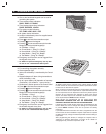
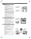
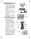
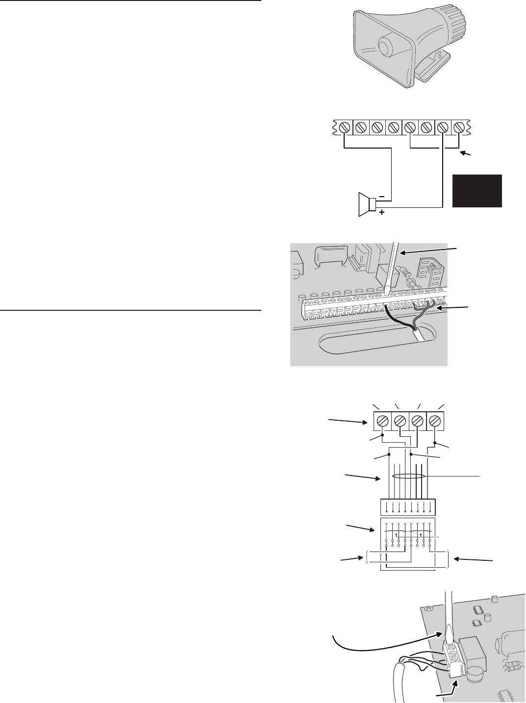
EXTERNAL ALARM SIREN CONNECTION
✦ An external siren alerts occupants and neighbors
with a loud siren during alarm.
✦ Use a 12 volt, 1 amp maximum rated weather-
resistant horn speaker with a built-in siren driver.
Do not use a plain speaker without a siren driver.
✎ NOTE: Connection of an electromechanical bell or
motor bell is not recommended because of the radio
interference generated when the bell is running.
✎ UL NOTE: Only one external siren is allowed in UL
installations.
1. Mount the external siren.
2. Route the wires from the external siren to the
Control Panel.
3. Route the siren wires up through the wiring access
slot or through a knockout when using conduit.
4. Connect a jumper wire from the +12 VDC terminal
to the RLY COM terminal.
5. Connect the positive siren wire to the RELAY
N/O terminal.
6. Connect the negative siren wire to one of the
COM terminals.
✎ NOTE: The relay contacts are isolated. Use the
RLY N/O & RLY COM terminals alone to switch an
externally powered load.
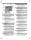
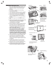
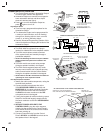
TELEPHONE LINE CONNECTION
✦ Connect the Control Panel to the telephone
line if the system is monitored, requires 2-way
audio, telephone remote command, or for remote
programming with RA-2400 software.
✦ Telephone RING & TIP terminals are for
connection to the incoming telephone line.
✦ Seized telephone ring & tip (R1 & T1) are for
connection to local telephone sets. When the
communicator activates, all the local telephone
sets will be disconnected to prevent an off-hook
telephone on the premises from blocking the
communicator call.
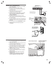
1. Install a USOC RJ31-X or RJ38-X jack to the
telephone system near the Control Panel.
2. Route an appropriate modular telephone line
cord from the jack to the Control Panel.
3. Route the line cord through the Control Panel's
wiring access slot or through a knockout for
conduit wiring.
4. Connect the incoming telephone line wires to the
Control Panel's telephone terminal block TIP and
RING terminals.
5. Connect the local telephone set wires to the Control
Panel's telephone terminal block T1 and R1 terminals.
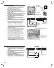
✦ When directly connecting (without a telephone line)
to the DUAL 824 with the RA-2400 remote access
software (Version 1.3 or later), disconnect the
incoming telephone line and connect the modem
to the panel's TIP and RING terminals (with the
modem's red & green phone line wires). Press the
EMERGENCY key while in Test Mode to cause the
panel to connect to the modem.
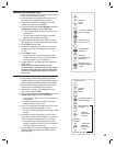
LOOP
8
H/A
-
H/A
+
RLY
COM
RLY
N/C
RLY
N/O
COM
EXTERNAL SIREN
12 VDC 1 AMP
MAXIMUM
EXTERNAL
ALARM RELAY
12 VDC, 1 AMP
MAXIMUM
INSTALL WIRE
JUMPER TO PROVIDE
POWER TO RELAY
CONTACTS
+12
VDC
MAIN TERMINAL BLOCK
CONNECT EXTERNAL
SIREN TO ALARM RELAY
TERMINALS
INSTALL A JUMPER
WIRE BETWEEN THE
+12 VDC AND RLY COM
TERMINALS
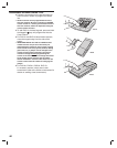
SEIZED
RING (R1)
SEIZED
TIP (T1)
LINE
RING (R)
LINE
TIP (T)
GRAY
RED
T
R
T1
R1
! " #
$
%
&
TO LOCAL
TELEPHONE
SETS
TO TELEPHONE
NETWORK
8-POSITION
USOC RJ31-X
(OR RJ38-X)
JACK
6
4
4
6
SHORTING BAR
SHORT REMOVED
ON PLUG
INSERTION
8-PIN
MODULAR
PHONE CORD
DUAL 824P
TELEPHONE
TERMINAL
BLOCK
GREEN
BROWN
BLUE, ORANGE
BLACK, AND
YELLOW NOT
USED
TELEPHONE TERMINAL BLOCK
CONNECT INCOMMING AND
OUTGOING TELEPHONE LINES
TO THE TELEPHONE TERMINAL BLOCK
TELEPHONE
TERMINAL
BLOCK
EXTERNAL
ALARM
SIREN