


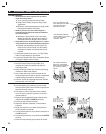
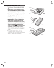
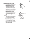
12
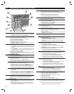
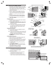
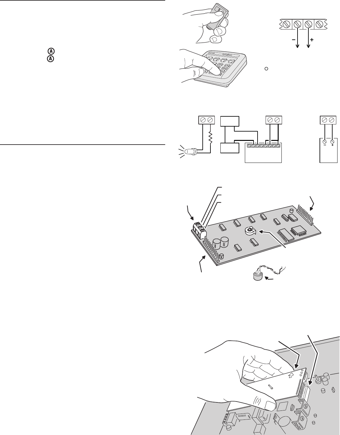
AUTOMATION OUTPUT CONNECTION
✦ The Control Panel provides a Automation Output
to control lights, devices and appliances.
✦ Automation Output can connect to most popular
home automation devices and other simple
electronic devices (see fi gure).
✦ Press
to turn the Automation Output on,
press
again to turn it off.
Programmable Options
✦ There are many programmable options for the
Automation Output.
✦ The Automation Output can be programmed for
a variety of useful functions, such as: fl ashing
during alarm, fl ashing after an alarm, on while
armed, or, on during exit/entry delays.
✦ See the “Advanced Programming” section of this
manual for details on changing the function of the
Automation Output.
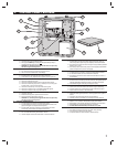
VOICE RESPONSE MODULE
✦ The DUAL 824P circuit board has a plug-in
location for a Model VB-2 voice response module.
✦ The VB-2 module allows remote command
of the system locally and remotely through a
pushbutton telephone.
✎ NOTE: The following two features require a Model
RSM-2 speaker/microphone kit installed in the
keypad.
✦ The VB-2 module can sound voice prompts
through a speaker installed in the keypad.
✦ The VB-2 module supports listen-only audio,
two-way manual audio, and full duplex two-way
audio communication with the Central Station
through a microphone installed in the keypad.
✎ NOTE: Refer to the VB-2 instructions for details on
operating the voice response module.
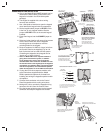
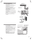
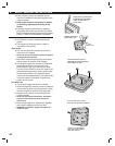
Voice Response Module Installation
1. Identify the audio module components, noting the
terminal block positions.
2. Connect shielded microphone wire to the
VB-2 MICROPHONE COMMON (for shield) and
MICROPHONE #1 (for center conductor) terminals.
Connect the other end of the wire’s shield to
the BLACK, and center conductor to the RED
microphone wires in the keypad.
3. If using two keypads for audio monitoring, repeat
Step 2 for the second keypad, except connect
the center conductor to the VB-2 MICROPHONE #2
terminal.
4. WITHOUT POWER APPLIED TO THE
CONTROL PANEL, plug the voice response
module into the sockets on the Control Panel's
circuit board. Be sure the arrows on the module
board are pointing up.
5. Connect 2-conductor wire from the Control
Panel’s KPD SPK+ and KPD SPK- terminals to the
two speaker wires in the keypad.
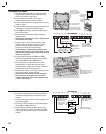
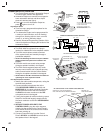
LOOP
8
H/A
-
H/A
+
RLY
COM
MAIN TERMINAL BLOCK
ANY SENSOR CAN
BE PROGRAMMED
TO TOGGLE
THE AUTOMATION
OUTPUT
PRESS THE
KEY ON ANY
SYSTEM KEYPAD
TO TOGGLE THE
AUTOMATION
OUTPUT
A
THE POSITIVE H/A TERMINAL PROVIDES
+12 VOLTS DC AND IS CURRENT LIMITED
AT 40 MILLIAMPS MAXIMUM
THE NEGATIVE H/A TERMINAL WILL
SWITCH TO GROUND WHEN
AUTOMATION OUTPUT IS ACTIVATED
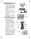
X-10
BURGLAR ALARM
INTERFACE
(CAN CONTROL
HOUSE LIGHTS
THROUGH X-10
SYSTEM)
X-10
LINEAR RB-90
RELAY MODULE
YOUR
LOAD
POWER
SOURCE
LIGHT
EMITTING
DIODE
(L.E.D.)
EXAMPLE AUTOMATION OUTPUT HOOK-UPS
H/A +
H/A -
H/A +
H/A -
H/A +
H/A -
470 OHM
MICROPHONE
TERMINALS
MICROPHONE #1 (+)
MICROPHONE COMMON (-)
MICROPHONE #2 (+)
MICROPHONE
DIGITAL VOICE
VOLUME CONTROL
MODULE-TO-CONTROL
PANEL CONNECTOR
MODULE-TO-CONTROL
PANEL CONNECTOR
VB-2 VOICE RESPONSE MODULE
CAREFULLY PLUG VOICE MODULE
INTO THE TWO CIRCUIT BOARD SOCKETS
BE SURE ALL
PINS ARE ALIGNED
BOARD ARROWS
POINT UP
BE SURE CONTROL PANEL POWER IS DISCONNECTED!