


50
6. If voltage is not correct, replace processor board.
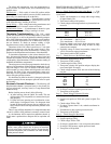
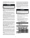
Step 7 — Potentiometer Connection Checkout
1. Turn power to OFF position.
2. Remove plug connection from pin terminal strip J3.
3. Connect negative meter lead to terminal 2 of J3.
4. Turn switch to ON position and go into Quick Test mode.
5. Place the other lead on terminals shown in table below,
and check voltage at pin terminals on terminal connector
J3:
*Voltage reading is dependent on the meter’s impedance. Readings
may vary with different meters.
6. If voltage is not correct, replace processor board.
Step 8 — Thermistor Input Connector Checkout
1. Turn power to OFF position.
2. Remove the thermistor connections from pin terminal
connector J1, and mark them for later replacement.
3. Connect the negative test lead to test pin TP18.
4. Turn power to ON position, and enter the Quick Test
routine.
5. Place the other lead on terminals shown in Table 25, and
check the voltages.
6. If voltages are incorrect (per Table 25), replace processor
board.
7. Turn power to OFF position, and replace the thermistor
connections removed in Step 2.
8. Turn power to ON position.
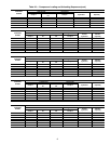
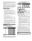
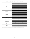
Table 25 — Pin Terminal Connector J1 Voltages
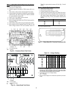
Step 9 — Thermistor Input Connector Checkout
1. Turn power to OFF position.
2. Disconnect all plugs for pin terminal connector J2 and
mark them for later replacement.
3. Connect a negative test lead to test pin TP18.
4. Turn power to ON position, and enter the Quick Test
routine.
5. Place the other lead on terminals shown in Table 26, and
check the voltages.
6. If voltages are incorrect (per Table 26), replace processor
board.
7. Turn power to OFF position, and replace the plugs re-
moved in Step 2.
8. Turn power to ON position.
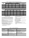
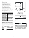
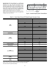
Table 26 — Pin Terminal Connector J2 Voltages
If Steps 1 through 9 have been competed and the unit still
will not function properly, replace the processor board.
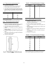
PIN TERMINAL VOLTAGE (DC)
1* 2.5
35
65
8* 2.5
10* 2.5
12 5
13* 2.5
14* 2.5
PIN
TERMINAL
VOLTAGE
(vdc ± 0.25 v)
1
0
2
5
6
0
7
5
8
0
9
5
10
0
11
5
12
0
13
5
14
0
15
5
16
0
17
5
18
0
19
5
20
0
21
5
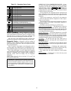
PIN
TERMINAL
VOLTAGE
(vdc ± 0.25 v)
1
0
2
5
3
0
4
5
7
0
8
5
9
0
10
5
13
0
14
5
15
5
17
5
18
5
19
5
20
5
21
5
22
5
23
5
24
5
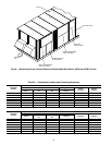
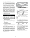
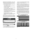
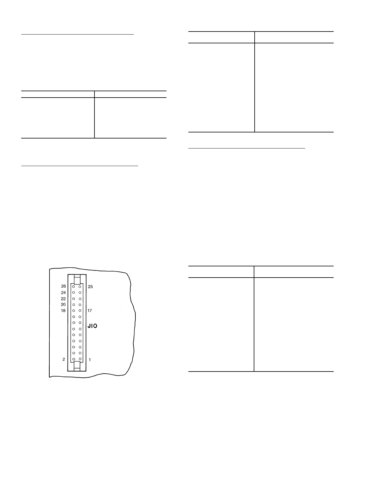
Fig. 52 — Display Board Pin Terminal Connector
(J10)