


29
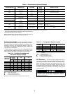
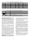
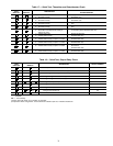
DETERMINE VFD SET POINT — The unit of measure for
the Duct Pressure set point at the VFD is output frequency
(Hz), corresponding to the desired DP set point (DPSP) in
inches of water gage (in. wg). To convert desired DPSP into
the VFD set point, refer to Table 13. Locate the pressure value
in the table closest to the desired DPSP for this installation
and use the corresponding VFD set point (Hz) value. If neces-
sary, interpolation between duct static pressure values is
permissible.
ADJUST VFD SET POINT — To adjust the VFD set point,
the VFD must be powered; however, since it is located near the
supply fan and motor, operation of the fan and motor is not
desirable. Either disable the Supply Fan or install the accessory
VFD remote display accessory.
DISABLE SUPPLY FAN MOTOR — To disable the supply
fan motor and change programming of VFD set point:
1. Turn off Indoor Fan Circuit Breaker (IFCB). This will re-
move power to the VFD.
2. Wait for the VFD display to go blank and remove VFD
cover without touching any interior components.
3. Ensure that the charge indicator lamp is out which indi-
cates that the VFD is discharged. The lamp is located on
the upper right hand corner of the terminal block. If still
lit, wait until lamp goes completely out. This may take
several minutes.
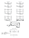
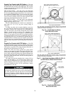
4. Remove jumper from terminals ST-CC (see Fig. 41) and
replace VFD cover.
5. Turn on IFCB.
6. The drive output will now be disabled but the program-
ming can be changed.
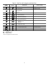
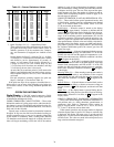
7. Change VFD set point according to Table 14 shown
on page 30.
8. Once the program changes are completed, turn off IFCB.
9. Wait for the VFD display to go blank and remove VFD
cover without touching any interior components.
10. Ensure that the charge indicator lamp is out which indi-
cates that the VFD is discharged. The lamp is located on
the upper right hand corner of the terminal block. If still
lit, wait until lamp goes completely out. This may take
several minutes.
11. Replace jumper to terminals ST-CC.
12. Replace VFD cover.
13. Turn on IFCB to enable the drive.
For additional information on the VFD (including basic
troubleshooting, factory jumper arrangements, and Carrier fac-
tory defaults programming), refer to Troubleshooting, Supply
Fan Variable Frequency Drive section (page 52).
Ensure the “CHARGE” lamp on the VFD is unlit. This
may take up to 4 minutes. The “CHARGE” lamp indicates
that the main capacitors in the VFD are charged. Internal
components of the VFD should not be touched until the
“CHARGE” lamp is completely out. Electrical shock can
cause injury or death.
IMPORTANT: The Carrier factory default values for the
VFD may be different than the default values of the
manufacturer. Refer to the Service section when check-
ing default values.
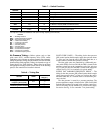
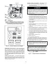
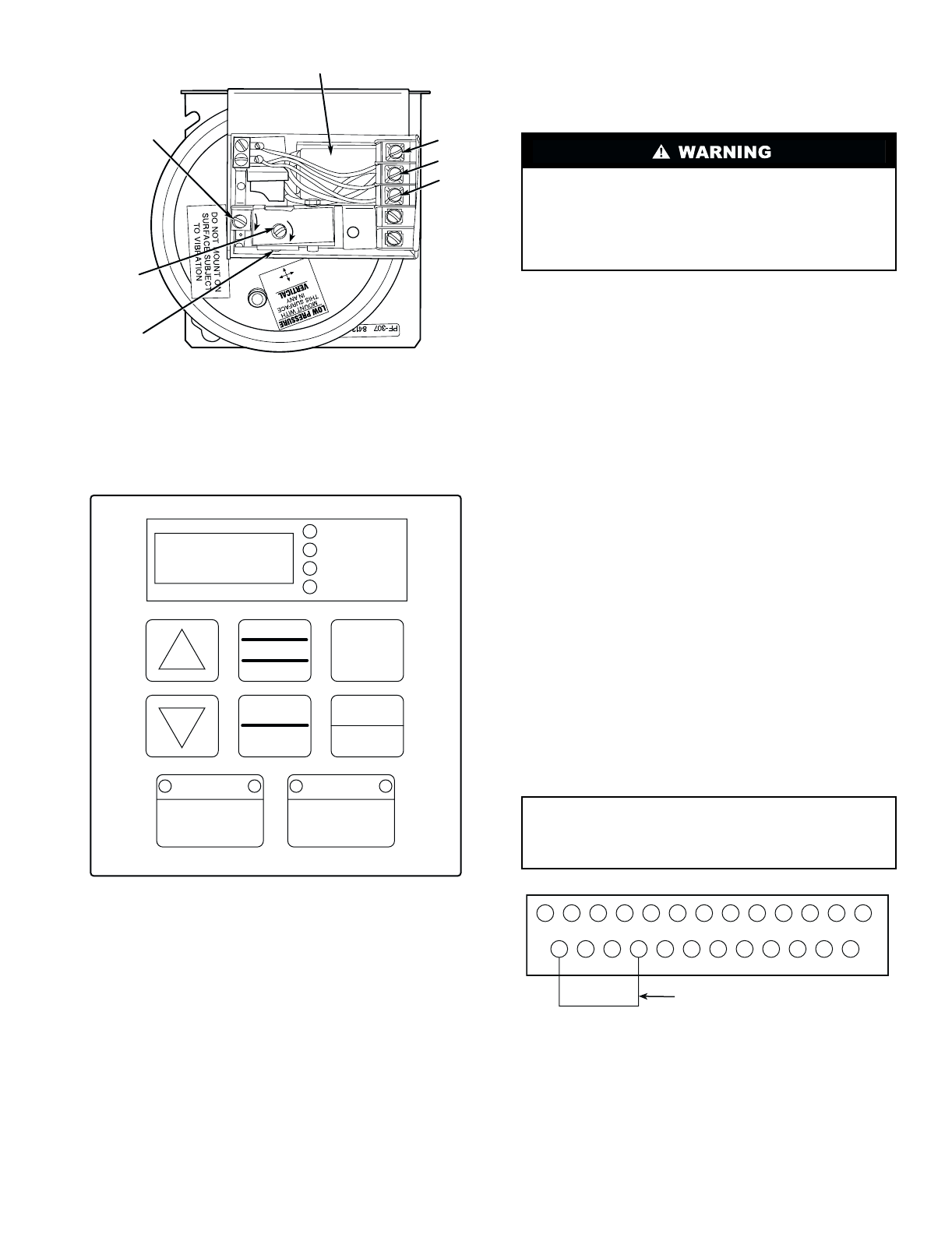
NULL DECREASE
SET POINT
DECREASE
PLANE
SET
POINT
INDICATOR
SET
POINT
ADJUSTMENT
NULL
ADJUSTMENT
COM
N.C.
N.O.
CAPACITOR
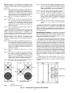
HZ
PERCENT
SECONDS
KW/AMPS/VOLTS
LOCAL/REMOTE
SPEED CTRL
MANUAL/AUTO
RUN MODE
SETUP
PROGRAM
MONITOR
STOP
RESET
READ
WRITE
RUN
LEGEND
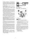
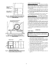
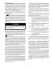
Fig. 39 — Differential Pressure Switch for Inlet
Guide Vane and Static Pressure Control Option
and Modulating Power Exhaust Option
COM —
Common
N.C. —
Normally Closed
N.O. —
Normally Open
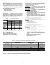
Fig. 40 — Variable Frequency Drive Keypad
P24 RES RR F R S1 S2 S3 S4 RCH P24 LOW LOW
ST FM AM CC CC RX PP IV FP FLC FLB FLA
REMOVE
JUMPER
Fig. 41 — Jumper Removal to Disable Motor