


3
The VAV control system monitors and controls the follow-
ing functions of the rooftop unit:
• supply-air temperature (unit capacity)
• morning warm-up or electric heat (if equipped)
• head pressure control, fan cycling
• economizer position
• diagnostic display
• unit check-out (quick test)
• supply air temperature reset (if equipped)
• demand limiting (if equipped)
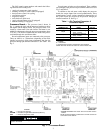
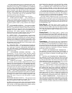
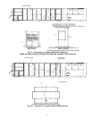
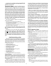
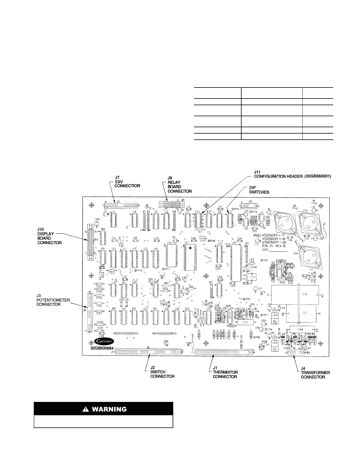
Processor Board —
The processor board, shown in
Fig. 1, contains the logic and the necessary hardware to drive
the outputs and the display board. The processor board is en-
closed by a sheet metal cover and a heater. The heater is con-
trolled by a thermostat to keep the processor temperature above
32 F (0° C). All electrical connections are made to the proces-
sor board through wire and ribbon cables.
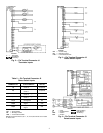
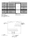
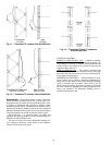
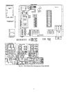
Several temperature inputs are connected to the processor.
There are either 4 or 5 thermistors (depending on the field-
installed accessories) which input temperature data into the
processor through pin terminal connector J1. See Table 1 and
Fig. 2.
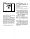
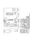
Several status switches are also monitored. These switches
are connected to the processor at pin terminal connector J2. See
Fig. 3 and Table 2.
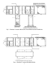
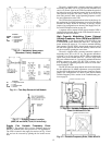
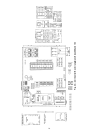
In addition to the unit status switch inputs, the processor
board also accepts inputs from several potentiometers. These
potentiometers control various operational characteristics of
the system. Inputs are received by the processor through pin
terminal connector J3. See Fig. 4.
Table 1 — Pin Terminal Connector J1
Thermistor Inputs
LEGEND
T —
Thermistor
*If equipped with accessory temperature reset package.
NOTE: Terminal numbers 3-13 are not used on these units.
CONNECTOR J1
TERMINAL NO.
TEMPERATURE
INPUT
UNIT SIZE
034-104
1,2
Reset Temperature* T10
14,15
Saturated Condensing
Temp., Circuit 2
T4
16,17
Saturated Condensing
Temp., Circuit 1
T3
18,19
Return-Air Temperature T2
20,21
Supply-Air Temperature T1
Fig. 1 — Processor Board
LEGEND
DIP —
Dual In-Line Package
EPPOM —
Erasable, Programmable Read-Only Memory
EXV —
Electronic Expansion Valve
Do not remove label covering EPROM. Removal causes pro-
gram to be erased.
*EPROM HT204485-1-XX where “XX” is the current revision
number.
NOTE: Processor Board is positioned in unit with J3 and J10
connections at the bottom.