


30
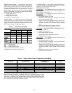
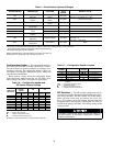
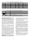
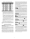
Table 13 — VFD Set Point (Frequency Command) for Duct Pressure
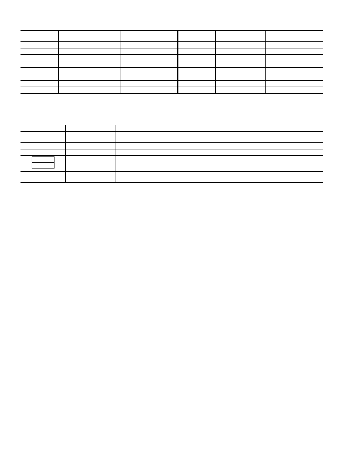
Table 14 — Changing the VFD Set Point (Frequency Command)*
*Choose set point from Table 13 according to desired duct pressure or Table 15 according to desired building pressure.
Modulating Power Exhaust (Option or Acces-
sory) (48FK,JK and 50FK,JK Units) —
The Mod-
ulating Power Exhaust system will maintain space pressure by
modulating power exhaust fan no. 1 and staging power exhaust
fan no. 2. Building pressure set point is established at the mod-
ulating power exhaust differential pressure switch (DPS).
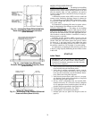
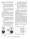
SIZE 034-048 UNITS — The modulating power exhaust dif-
ferential pressure switch is located in the auxiliary control box
mounted in the corner next to the power exhaust motor door.
To gain access to this control box, remove the auxiliary control
box cover. When replacing cover, be sure to properly secure it
in order to prevent water from being drawn into the unit. See
Fig. 33.
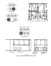
SIZE 054-104 UNITS — The modulating power exhaust dif-
ferential pressure switch is mounted below the auxiliary con-
trol box next to the access door labeled FILTER SECTION.
See Fig. 35.
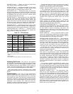
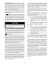
DIFFERENTIAL PRESSURE SWITCH — The modulating
power exhaust DPS has a set point range of 0.5 in. wg to
–0.5 in. wg. Factory setting is +0.1 in. wg. To adjust set point,
turn set point adjusting screw (see Fig. 39) clockwise to
decrease set point and counterclockwise to increase set point.
This switch also has an adjustable null span. The null span is
the pressure change that can be made without contacts opening
or closing. It is adjustable from 0.06 in. wg to 0.14 in. wg when
set point is at minimum position (–0.5 in. wg) and 0.07 in. wg
to 0.14 in. wg when set point is at maximum position
(+0.5 in. wg). To adjust null span, turn null adjusting screw
(Fig. 39) clockwise to decrease span and counterclockwise to
increase span. All switches leave factory with null span set at
maximum position. The smaller the null span, the closer the
pressure will be maintained to desired set point.
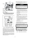
High Capacity Power Exhaust (48FM and
50FM,FS Units) —
The power exhaust VFD will modu-
late the power exhaust fan motor no. 1 speed and stage (on/off)
power exhaust fan motor no. 2 to maintain the building pres-
sure. The set point for the building pressure control is set at the
power exhaust VFD using the keyboard on the front of the
power exhaust VFD enclosure. See Fig. 40.
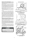
NOTE: The VFD will always provide the proper phase
sequences to the power exhaust fan motor.
The exhaust fan motor operates in proper rotation regardless
of the phase sequence to the unit. If, upon start-up, the outdoor
fans operate backwards but the exhaust fan operates in the cor-
rect direction, reverse any two leads on the main terminal
block. All fans will then operates in the correct direction.
The building pressure transducer has a range of –0.5 to
+0.5 in. wg. The output is a 4 to 20 mA signal, scaled to this
range. The VFD translates the 4 to 20 mA signal to represent a
frequency value over the control range of 0 to 60 Hz. See
Table 15. The set point for duct pressure control is established
at the power exhaust VFD keypad in terms of Hz. The factory
default set point is 30 Hz, representing a building pressure of
0.0 in. wg.
DETERMINE POWER EXHAUST VFD SET POINT —
The unit of measure for the building pressure set point (BPSP)
at the power exhaust VFD is output frequency (Hz), represent-
ing the desired BPSP (in. wg). To convert the desired BPSP
into the power exhaust VFD set point, refer to Table 15. Locate
the pressure value in the table closet to the desired BPSP for
the application and use the corresponding set point (Hz) value.
If necessary, interpolation between duct static pressure values
is permissible.
ADJUST PE VFD SET POINT — To adjust the PE VFD set
point, the PE VFD must be powered. Since it is located in the
indoor section of the unit, use caution to ensure that the service
access door is blocked open and will not close suddenly.
Change PE VFD set point according to Table 14.
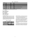
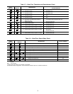
PRESSURE
(in. wg)
VFD SET POINT (Hz)
CONTROL SIGNAL
(mA)
PRESSURE
(in. wg)
VFD SET POINT
(Hz)
CONTROL SIGNAL
(mA)
0.00
04.0
2.00
24 10.4
0.25
34.8
2.25
27 11.2
0.50
65.6
2.50
30 12.0
0.75
96.4
2.75
33 12.8
1.00
12 7.2
3.00
36 13.6
1.25
15 8.0
3.25
39 14.4
1.50
18 8.8
3.50
42 15.2
1.75
21 9.6
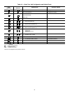
KEY OPERATION LED MESSAGE EXPLANATION
XX.X or OFF
Standard Monitor Mode (output frequency). If drive is disabled, display
will read “OFF”. If enabled, display will show current output frequency
↓
60.0 Pressing arrow key once will display the current frequency set point
↓↑
45.0 (flashing) Pressing up/down arrow keys changes the desired set point
FC and 45.0 (flashing)
When the Read/Write key is pressed, the parameter name (FC) and the new value (45.0)
will alternately flash to indicate that the new value has been stored. After 2 cycles, the display will
return to the standard monitor mode.
XX.X or OFF
Standard Monitor Mode (output frequency). If drive is disabled, display
will read “OFF”. If enabled, display will show current output frequency
READ
WRITE