


28
Supply Fan Control with IGV Option —
The inlet
guide vane option will modulate the supply fan airflow in order
to maintain the static pressure in the supply duct. The set point
for duct static pressure is established at the differential pressure
switch for the IGV control.
SIZE 034-048 UNITS — The inlet guide vane differential
pressure switch is located in the auxiliary control box mounted
in the corner under the side air hood that is next to the access
door marked FILTER SECTION. To gain access to this control
box, remove the auxiliary control box cover. When replacing
cover, be sure to properly secure it in order to prevent water
from being drawn into the unit. See Fig. 36 and 37.
SIZE 054-104 UNITS — The inlet guide vane differential
pressure witch is mounted on an upright located behind the
supply-fan motor. See Fig. 36-38.
The IGV differential pressure switch has an adjustable set
point range of 1.1 to 3.5 in. wg. and a factory setting of
1.9 in. wg.
To adjust set point, turn set point adjusting screw (see
Fig. 39) clockwise to decrease set point and counterclockwise
to increase set point. This switch also has an adjustable null
span. The null span is the pressure change that can be made
without contacts opening or closing. It is adjustable from
0.06 in. wg to 0.17 in. wg when set point is at minimum posi-
tion (1.1 in. wg) and 0.11 in. wg to 0.31 in. wg when set point is
at maximum position (3.5 in. wg). To adjust null span, turn a
null adjusting screw (Fig. 39) clockwise to decrease span and
counterclockwise to increase span. All switches leave factory
with null span set at maximum position. The smaller the null
span, the closer the pressure will be maintained to desired set
point.
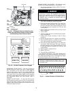
Supply Fan Control with VFD Option —
The VFD
option will modulate Supply Fan motor (and thus wheel) speed
to maintain the static pressure in the ductwork. Set point for the
VFD option is set at the VFD, using the display keyboard on
the front of the VFD enclosure. See Fig. 40.
NOTE: The VFD will always provide the proper phase
sequence to the supply-fan motor. The supply-fan motor oper-
ates in proper rotation regardless of the phase sequence to the
unit. If, upon start-up, the outdoor fans operate backwards but
the supply fan operates in the correct direction, reverse any two
leads to the main terminal block. All fans will then operate in
the correct direction.
The supply duct pressure transducer has a range of 0.0 to
5.0 in. wg. Its output is a 4 to 20 mA signal, scaled to this
range. The VFD translates this 4 to 20 mA input signal to rep-
resent a frequency value over the control range of 0 to 60 Hz.
The factory default set point is 30 Hz, representing a supply
duct pressure of 2.5 in. wg.
Factory-installed optional VFD is located near the supply
fan and motor. During any service work or programming at
the VFD, operation of the fan and motor is not desirable
and may be dangerous. Either disable the unit supply fan
(following instructions below) or install the accessory VFD
remote display accessory.
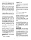
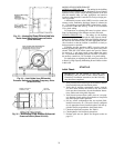
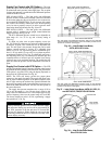
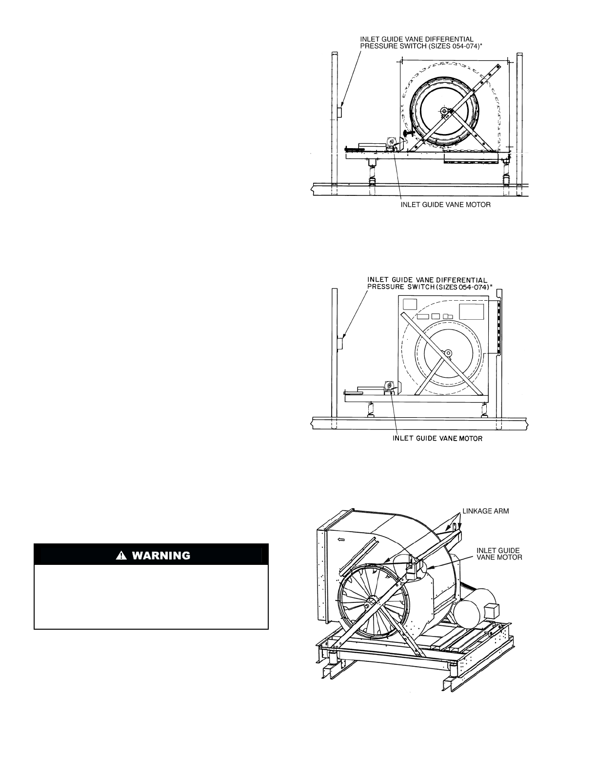
*The inlet guide vane differential pressure switch for the 034-048
units is located in the back of the unit in the auxiliary control box. Its
location is not shown in this figure.
Fig. 36 — Inlet Guide Vane Motor,
50FK,JK034-074 Units
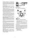
*The inlet guide vane differential pressure switch for the 034-048
units is located in the back of the unit in the auxiliary control box. Its
location is not shown in this figure.
Fig. 37 — Inlet Guide Vane Motor, 48FK,JK, 50FJ,JY,
and 50FJX,FJY,FKX,FKY034-074 Units
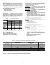
Fig. 38 — Inlet Guide Vane Motor,
Size 078-104 Units