


17
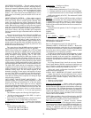
EXAMPLE:
T10 desired set point is 70 F.
T10
R
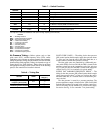
from Table 4 for 70 F is 5929 ohms.
P7
R
= 13,084 – 5929
P7
R
= 7155 ohms
Using an ohmmeter, set the P7 potentiometer to 7155 ohms
to achieve a reset initiation set point of 70 F.
Potentiometer P3
— Reset limit set point (maximum tempera-
ture value for modified supply air set point). Maximum of 70 F,
minimum 40 F. Set between leaving air set point (P1) and 70 F
(maximum range permitted by control).
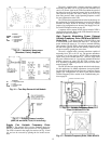
OPERATING SEQUENCE — If space temperature is above
reset set point (T10 > P7), no reset will occur.
If space temperature is equal to or less that reset set point
(T10 < P7), the LED will display 20 and reset will begin.
Control will automatically adjust leaving air temperature by
the following formula:
MSP = SP + [(P3 - SP) / 3] x (P7 – T10)
where:
MSP = Modified Leaving-Air Set Point
SP = Supply-Air Set Point
P3 = Maximum Supply-Air Temperature (reset limit)
P7 = Reset Initiation Temperature (reset set point)
T10 = Actual Space Temperature
3 = Ratio for reset (F) (fixed parameter)
Table 4 — Thermistor Resistance and Voltage
Drop Characteristics
TEMP
(F)
RESISTANCE
(Ohms)
VOLTAGE
DROP (v)
31.0
16813.8 3.582
32.0
16345.7 3.553
33.0
15892.2 3.523
34.0
15452.7 3.494
35.0
15026.7 3.464
36.0
14613.9 3.434
37.0
14213.6 3.404
38.0
13825.5 3.373
39.0
13449.2 3.343
40.0
13084.2 3.312
41.0
12730.1 3.281
42.0
12386.6 3.250
43.0
12053.3 3.219
44.0
11730.0 3.187
45.0
11416.1 3.156
46.0
11111.5 3.124
47.0
10815.8 3.093
48.0
10528.7 3.061
49.0
10250.0 3.029
50.0
9979.3 2.997
51.0
9716.5 2.965
52.0
9461.3 2.933
53.0
9213.4 2.901
54.0
8972.6 2.869
55.0
8738.6 2.837
56.0
8511.4 2.805
57.0
8290.6 2.772
58.0
8076.1 2.740
59.0
7867.7 2.708
60.0
7665.1 2.676
61.0
7468.3 2.644
62.0
7277.1 2.612
63.0
7091.2 2.581
64.0
6910.6 2.549
65.0
6735.1 2.517
66.0
6564.4 2.486
67.0
6398.6 2.454
68.0
6237.5 2.423
69.0
6080.8 2.391
70.0
5928.6 2.360
71.0
5780.6 2.329
72.0
5636.8 2.299
73.0
5497.0 2.268
74.0
5361.2 2.237
75.0
5229.1 2.207
76.0
5100.8 2.177
77.0
4976.0 2.147
78.0
4854.8 2.117
79.0
4736.9 2.088
80.0
4622.4 2.058
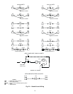
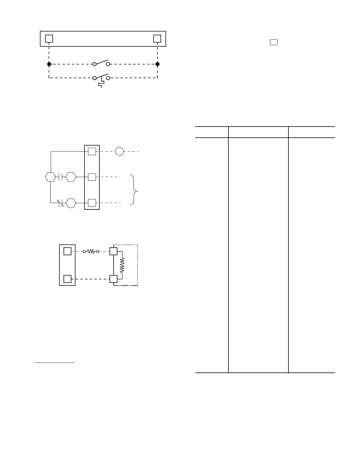
034-048: TB3
054-104: TB4
034-048: TB3
054-104: TB4
OCCUPIED/UNOCCUPIED
SWITCH
NIGHT SETBACK THERMOSTAT
1
2
4
6
5
7
N.C.
N.O.
V
FIELD
SUPPLIED
POWER
SOURCE
SIGNAL
TO ROOM
TERMINALS
034-048: TB3
054-104: TB4
3
4
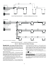
NOTES:
1. Occ/Unocc switch closes when occupied.
2. Night setback thermostat closes when in night setback heating.
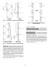
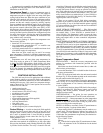
Fig. 23 — Occupied/Unoccupied Switch with
Night Setback Thermostat
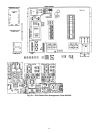
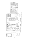
Fig. 24 — Heat Interlock Relay
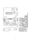
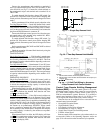
Fig. 25 — Accessory Reset Board
034-048: TB3
054-104: TB4
12
15
P7
RESET
BOARD
T10