


56
POWER EXHAUST FAN MOTOR NO. 1 OVERLOAD
PROTECTION — The VFD provides operating overload
protection for the supply fan motor. The factory has pro-
grammed the power exhaust VFD overload function to match
the factory-installed motor (motor size and efficiency). If the
power exhaust fan motor is changed from the original factory
selection, the overload value may need to be changed by the
service person. Contact your local Carrier representative for
assistance in determining the proper overload setting.
NOTE: Variable frequency drive size is matched to factory-
installed motor size. Do not increase motor size without also
changing to equivalent VFD size.
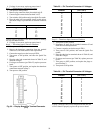
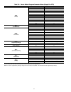
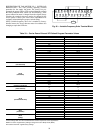
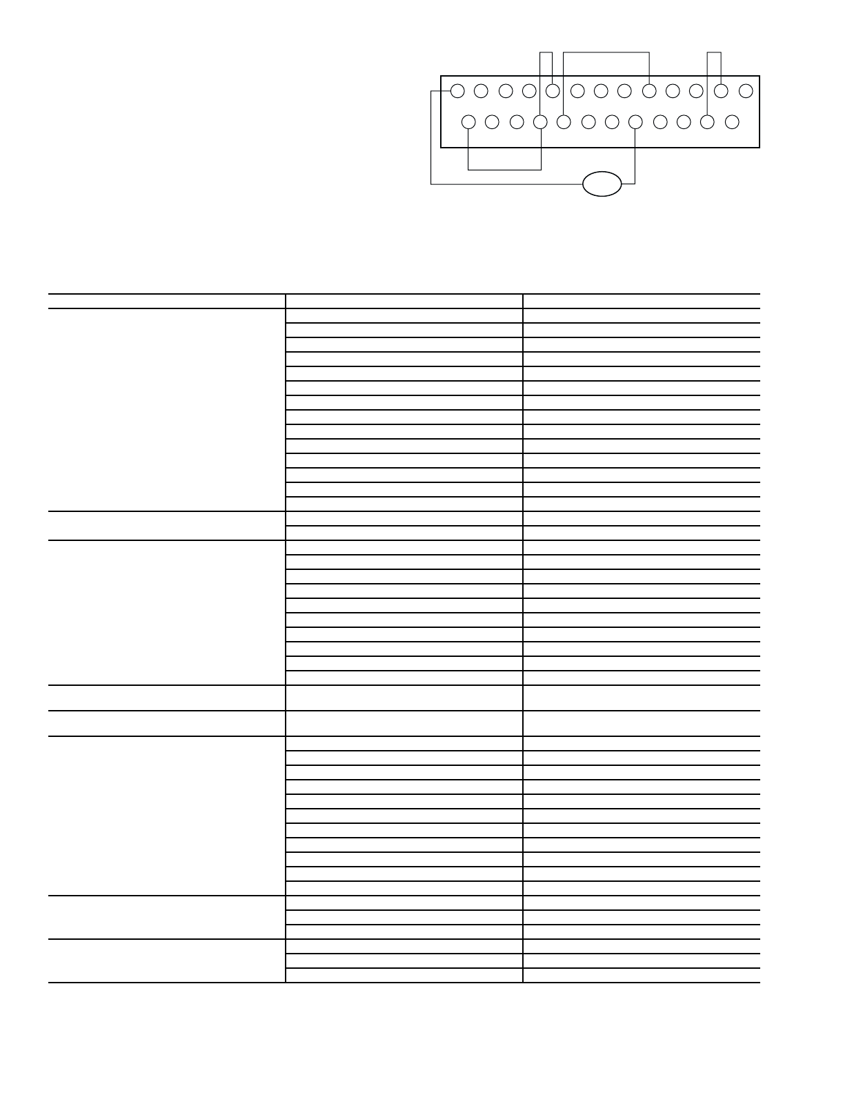
Table 33 — Carrier Power Exhaust VFD Default Program Parameter Values
*These settings differ from the Toshiba defaults and are required for Carrier applications.
NOTE: To restore original factory settings, change tYP to 6 in SEtup mode (SEtP).
This restores the VFD original factory settings.
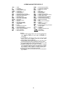
PARAMETER GROUP PARAMETER DEFAULT VALUE
SEtP
(Setup)
ACC1 60.0 Sec
DEC1 60.0 Sec
UL 59.8 Hz
LL 10.0 Hz*
Luln 1
P3 20%
F-P3 0.0 Hz
P4 98%
F-P4 60 Hz
tHr1 See Table 35
StC1 0
StL1 110%
OLN 1
tYP 5*
Gr.F
(Fundamental)
FH 60 Hz
Pt 12
Gr.Fb
(Feedback)
FbP1 1*
Fbin 2
GP .30
Gl 2 sec
GA 0
GFS 80
P1LL 10
PuL 1
PuUl 10
PuLL 10
Gr.SF
(Frequency Settings)
Fsor 60 Hz
Gr.Pn
(Panel Control)
Fr 0*
Gr.St
(Terminal Selection)
1t 1
1t0 0
1t1 56
1t2 13
1t3 3
1t4 10
Ot1 4*
Ot2 2*
Ot2d 5*
Ot2H 100*
LF 15*
Gr.Pr
(Protection)
UuC 1*
UuCt 2
ArSt 3
Gr.Ut
(Utility)
Cnod 1*
Fnod 2*
bLPn 1*
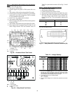
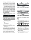
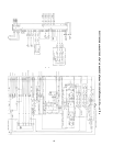
4-20mA
P24
RES
RR
F
ST
FM
AM
CC
CC
R
SI
RX
S2
S3
PP
S4
RCH
P24
LOW
LOW
FLA
FLB
FLC
FP
IV
C
A
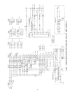
Fig. 56 — Variable Frequency Drive Terminal Block