


12
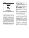
Supply Fan Variable Frequency Drive
(VFD) —
The optional VFD is used to modulate supply fan
airflow to maintain duct static pressure on VAV applications.
The VFD is located in the supply fan section (see Fig. 18 and
19), and can be accessed by opening the fan section access
door.
The unit is supplied with a pressure transducer capable of
measuring from 0.0 to 5.0 in. wg. The pressure transducer will
send a 4 to 20 mA signal to the VFD to modulate the speed of
the indoor fan motor to precisely control the fan to the desired
static pressure set point. The VFD is factory set at 2.5 in. wg
duct static pressure. Refer to the Operating Sequence section
for more information on the VFD.
The VFD has been programmed and wired at the factory for
this application. No further adjustments (except for Duct Static
Pressure Set Point) should be necessary at start-up. Factory
jumper wire configurations are shown in the Supply Fan Con-
trol with VFD Option section on page 28.
A separate service manual for the factory-installed VFD is
supplied with each unit. Refer to the VFD manual for more in-
formation on the VFD controls.
High Capacity Modulating Power Exhaust
Variable Frequency Drive (48FM and 50FM,FS
Units Only) —
The power exhaust VFD (PE VFD) is used
to modulate the power exhaust fan motor no. 1 and stage the
power exhaust fan motor no. 2 in order to maintain building
static pressure. The PE VFD is located at the return air end of
the unit of the opposite side from the auxiliary control box and
can be accessed by opening the access door.
The unit is supplied with a pressure transducer capable of
measuring from –0.5 to +0.5 in. wg. The pressure transducer
will send a 4 to 20 mA signal to the PE VFD to modulate the
speed of the power exhaust motor no. 1 and also stage on/off
the power exhaust motor no. 2 to precisely maintain the desired
building pressure set point. The PE VFD is factory set at
0 in. wg. Refer to Operating Sequence section for more infor-
mation on the PE VFD.
The PE VFD has been programmed and wired at the factory
for this application. No further adjustments (except for Build-
ing Pressure Set Point) should be necessary at start-up. Factory
jumper wire configurations are shown in the Power Exhaust
Variable Frequency Drive section in the Troubleshooting sec-
tion on page 55.
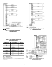
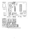
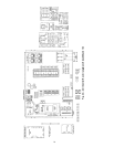
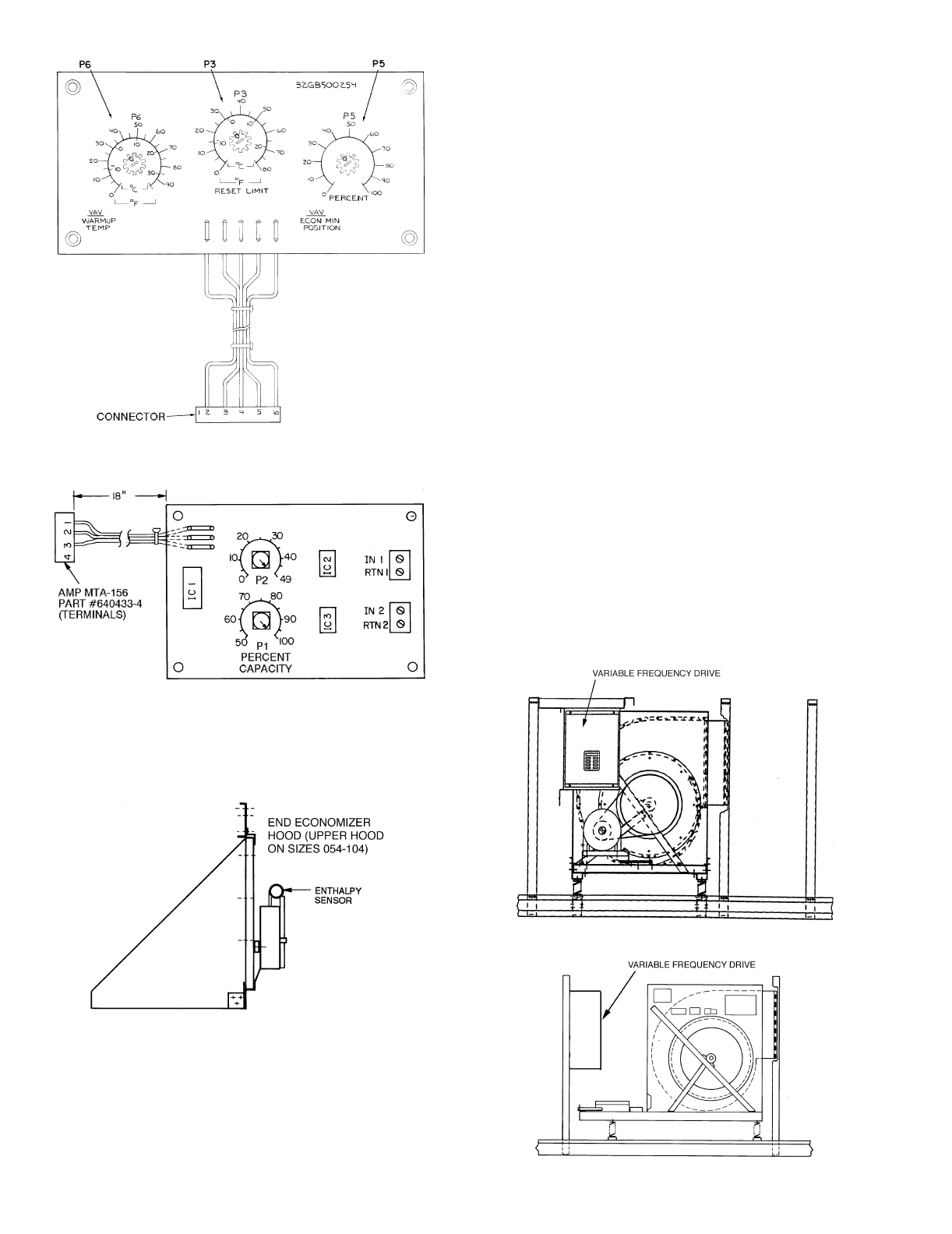
Fig. 15 — Accessory Relay Board
(Standard; Factory Supplied)
LEGEND
IC —
Integrated Circuit
IN —
Input
P—
Potentiometer
RTN —
Return
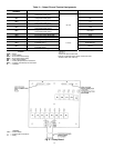
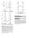
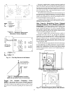
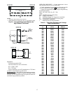
Fig. 16 — Two-Step Demand Limit Module
Fig. 17 — Enthalpy Sensor Location
(48FK,JK and 50FK,FY,JK,JY Units Only)
LEGEND
ECON —
Economizer
MIN —
Minimum
P—
Potentiometer
VAV —
Variable-Air
Volume
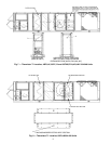
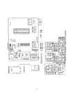
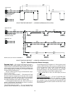
Fig. 18 — Variable Frequency Drive,
Sizes 034-048 and 078-104
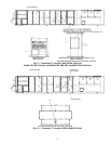
Fig. 19 — Variable Frequency Drive, Sizes 054-074