


55
VFD OPERATIONAL STATUS — The VFDs contain ex-
tensive self-diagnostic functions which are accessed through
the VFD display panel (located on the front of the VFD or at a
remote location when the accessory remote display package
has been installed).
When power is first supplied to the VFD, the display auto-
matically starts with the frequency monitor function of its stan-
dard monitor mode. In the frequency monitor function, the out-
put frequency is displayed. Push the S/P/M (Setup/ Program/
Monitor) key to switch to the Mode Selection menu. Push the
S/P/M key again to toggle the display back to the standard
monitor mode.
From the Mode Selection menu, the service person can
view all of the monitored status variables, including up to four
user-selected variables and any trip history in the memory.
Refer to the separate VFD Operation Manual for detailed
instructions on accessing diagnostic information, initiating
troubleshooting, and clearing any trip history.
RESTORING FACTORY VFD DEFAULTS — The original
factory configuration values are saved in the memory of the
VFD and can be restored by the service person if required.
There are two types of saved file data: Carrier-factory settings
(factory programmed settings made to the VFD which apply
specifically to the unit it is installed on) and standard defaults
for general Carrier unit use.
The Carrier-factory settings are maintained as user settings.
These can be restored by entering the Setup mode (in the
S/P/M menu) and setting parameter tYP = 6 on the keypad/
display. This will recall the specific factory defaults for this
unit.
Occasionally it may be necessary to restore the VFD de-
faults to the general Carrier use values. These are stored in an
OPTION ROM (read-only memory chip). However, some
variables may need to be manually changed to match the spe-
cific unit’s factory default settings. To recall the general Carrier
defaults, enter the Setup mode and set parameter tYP = 3. Re-
fer to Table 31 for items requiring manual adjustment.
Power Exhaust Variable Frequency Drive
(48FM and 50FM,FS)
NOTE: The VFDs (part no. TOSVERT130-E3) are specially
modified for use on Carrier equipment. Some specifications
and control configuration defaults for Carrier applications
will differ from the VFD manufacturer manual included in the
packet. See Table 33 for listing of Carrier-specific default
values.
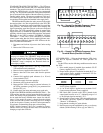
STANDARD TRANSDUCER CONTROL — The VFD
monitors and controls building pressure (BP) via a differential
pressure transducer. The pressure transducer is located in the
auxiliary control box. The pressure transducer’s high-pressure
reference port is connected to the outside of the unit cabinet by
a factory-installed tubing section. The pressure transducer’s
low-pressure reference point must be field-connected to the
building pressure pick-up (field-supplied and installed in the
building).
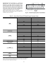
The BP transducer monitors the static pressure in the occu-
pied space and provides a 4 to 20 mA signal directly to the
power exhaust VFD. (Refer to Table 30 for transducer output
signal [mA] for actual building static pressure.) The internal
logic of the power exhaust VFD compares this signal repre-
senting actual duct pressure to the user-configured BP set
point. The power exhaust VFD automatically adjusts its output
to the power exhaust fan motor to maintain the desired BP set
point. When operating with the factory-standard BP transducer,
the internal PID logic of the power exhaust VFD is enabled.
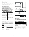
EXTERNAL SIGNAL CONTROL — If the power exhaust
VFD is to be controlled by an external control system other
than the factory-supplied pressure transducer, the internal PID
logic function of the power exhaust VFD must be disabled. To
disable the PID control:
1. Disconnect and lock out all power to the Carrier rooftop
unit.
2. Remove the VFD access cover.
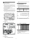
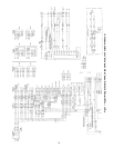
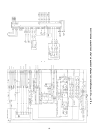
3. Install a jumper across S2-CC (see Fig. 56 for power ex-
haust VFD terminal board connections).
4. Remove factory-supplied cable attached to IV and CC.
5. Remove other end of the same cable from the pressure
sensor.
6. Connect field-supplied speed reference (4 to 20 mA)
across terminals IV-P24.
7. Disable the supply fan motor operation.
8. Reconnect power to the unit and power exhaust VFD.
9. Reprogram the power exhaust VFD to accept an external
reference (in the Utility parameters group [GR.Ut], set
parameter item Fnod [no.312] = 4).
10. Enable supply fan motor and return power to the unit.
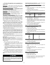
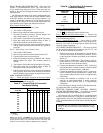
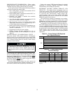
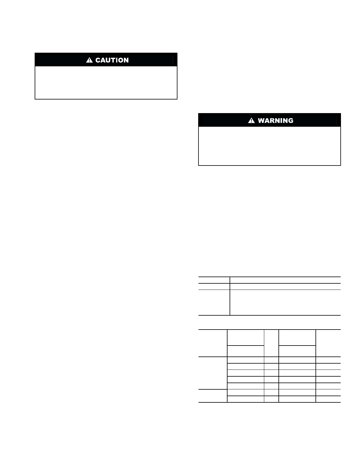
Table 31 — Supply Fan VFD Required
User Adjusted Defaults
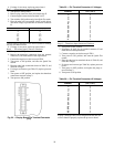
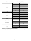
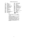
Table 32 — Supply Fan Motor Overload Settings
LEGEND
If using the VFD display panel, disconnect all power to
the unit and the VFD before entering unit, or use the
accessory remote display module. Disable supply fan and
motor operation before accessing VFD-mounted display
module.
Ensure the “CHARGE” lamp on the VFD is unlit. This
may up to 4 minutes. The “CHARGE” lamp indicates that
the main capacitors in the VFD are charged. Internal com-
ponents of the VFD should not be touched until the
“CHARGE” lamp is completely out. Electrical shock can
cause injury or death.
SIZES ITEM
All
Motor overload settings (see Table 32)
054-104
1. Check jumper CC-F
2. Gr.UT/bLSF = 1
3. Gr.SF/Sr.n = 1
4. Gr.SF/SrN1 = 0
5. SEtP/tYP = 5 (Save User Settings)
UNIT 48/50
UNIT
VOLTAGE
DESIGNATION
AND
IFM HP
DESIGNATION
tHr1
SETTING
Model No.
Position 12
Model No.
Position 15
FK,FY,
JK,JY
5 And N 82.0
5 And Q 86.0
6 And A 80.0
6 And K 80.0
6 And Q 80.0
FKX,FKY,
JKX,JKY
6 And Q 80.0
6 And T 78.0
IFM —
Indoor Fan Motor