


36
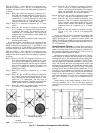
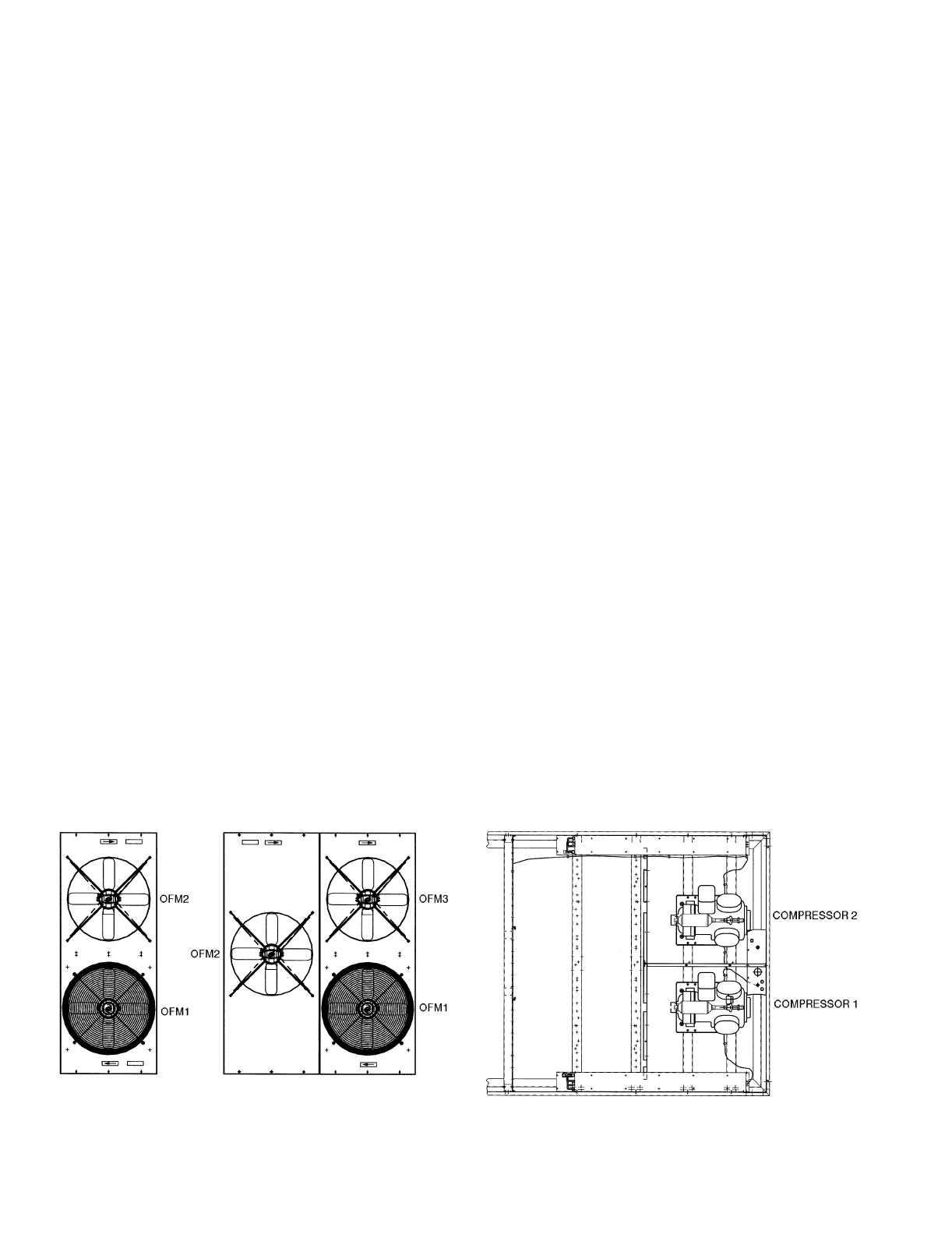
SIZE 044 UNITS — These units have 2 compressors and 1
unloader on compressor no. 1. See Fig. 42 for compressor and
condenser fan motor locations. The unit operating sequence is
as follows:
Stage 1 Relays K1 and K3 are energized. Compressor no. 1
starts with the unloader energized. Compressor no. 1
is running at
1
/
2
capacity. The crankcase heater on
compressor no. 1 has been deenergized, and the first
stage condenser fan has been energized. Outdoor
(condenser) fan motor no. 1 (OFM1) has started.
Stage 2 Relay K1 is energized. Compressor no. 1 is fully
loaded.
Stage 3 Relays K1, K3, and K5 are energized. Compressor
no. 1 is running at
1
/
2
capacity, and compressor no. 2
is running at full capacity. The crankcase heater for
compressor no. 2 is deenergized. The second stage
condenser fan has been energized. Both OFM1 and
OFM3 are operating.
Stage 4 Relays K1 and K5 are energized. Both compressors
are running fully loaded.
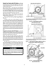
Size 044 units have one fan that can be controlled by the
processor. The other 2 are controlled by the compressors. The
OFM1 is energized by compressor no. 1, and OFM3 is ener-
gized by compressor no. 2. The OFM2 is cycled by the proces-
sor based on input from either circuit (thermistors T3 and T4).
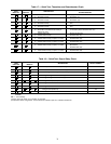
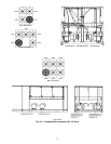
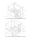
SIZE 104 UNITS — These units have 4 compressors and 1
unloader on compressor no. 1. See Fig. 43 for compressor and
condenser fan motor locations. The unit operating sequence is
as follows:
Stage 1 Relays K1 and K3 are energized. Compressor no. 1
starts with unloader energized. Compressor no. 1 runs
at
2
/
3
capacity. The crankcase heater for this compres-
sor has been deenergized, and first stage of condenser
fans has been energized. Outdoor (condenser) fan
motor no. 1 (OFM1) and outdoor fan motor no. 3
(OFM3) have started.
Stage 2 Relay K1 is energized. Compressor no. 1 is fully
loaded.
Stage 3 Relays K1, K3, and K5 are energized. Compressor
no. 1 runs at
2
/
3
capacity and compressor no. 2 is run-
ning at full capacity. The crankcase heater for com-
pressor no. 2 is deenergized. The first stage of
condenser fans on circuit 2 has been energized. Fans
OFM1, OFM2, OFM3, and OFM4 are operating.
Stage 4 Relays K1 and K5 are energized. Both compressors
no. 1 and no. 2 are running fully loaded.
Stage 5 Relays K1, K3, K5, and K5 are energized. Compres-
sor no. 1 runs at
2
/
3
capacity and compressors no. 2
and no. 4 are running at full capacity. The crankcase
heater on compressor no. 4 is deenergized. Fans
OFM1, OFM2, OFM3, and OFM4 are operating.
Stage 6 Relays K1, K5, and K6 are energized. Compressors
no. 1, no. 2, and no. 4 are running fully loaded.
Stage 7 Relays K1, K2, K3, K5, and K6 are energized. Com-
pressor no. 1 runs at
2
/
3
capacity and compressors no.
2, no. 3, and no. 4 are running at full capacity. Fans
OFM1, OFM2, OFM3, and OFM4 are operating.
Crankcase heater for compressor no. 3 is deener-
gized.
Stage 8 Relays K1, K2, K5, and K6 are energized. Compres-
sors no. 1, no. 2, no. 3, and no. 4 are running fully
loaded.
On size 104 units, the first 4 condenser fans energize with
the compressors; circuit no. 1 compressors control OFM1 and
OFM3, and circuit no. 2 compressors control OFM2 and
OFM4. The OFM5 and OFM6 are staged by the microproces-
sor based on condensing temperature input from either circuit’s
T3 or T4 thermistor.
Head Pressure Control —
All units have as standard a
basic head pressure control function which allows the units to
operate in cooling down to 45 F. If cooling is required at out-
door ambient temperatures lower than 45 F, refer to accessory
head pressure control literature for details.
Head pressure control is handled by the processor. The pro-
cessor attempts to maintain the head pressure by cycling the
condenser-fan motors. No condenser fans will be running with-
out a call for mechanical cooling. Thermistors T3 and T4 pro-
vide the condensing temperature information to the processor.
These VAV rooftop units have dual refrigeration circuits, and
the higher circuit temperature will govern unit operation. If the
condensing temperature is above 133 F (236 psig), a condenser
fan stage will be added. If the condensing temperature is 78 F
(142 psig) or less, the number of condenser fans operating will
be decreased. After each fan stage, the processor will wait one
minute for the head pressures to stabilize before changing
again, unless thermistor T3 or T4 senses a temperature greater
than 125 F (278 psig), in which case all condenser fans are
started.
During start-up, if the outdoor ambient is above 70 F (as
sensed by thermistor T3 or T4), the first-stage, processor-
controlled fans are turned on to prevent excessive discharge
pressures.
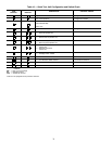
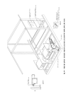
034 AND 038 UNITS
044 AND 048 UNITS
LEGEND
Fig. 42 — Component Arrangement, 034-048 Units
OFM —
Outdoor (Condenser) Fan Motor