


48
The failure will automatically reset once potentiometer re-
turns to normal. If a failure occurs, one of the following is the
probable cause:
DIP Switch 4
— If this switch is in the ON position and the
accessory board is not installed (accessory board is standard on
these units, so it should always be on the unit).
Incorrect Potentiometer Setting
— If potentiometer is turned
fully clockwise or counterclockwise, potentiometer will be out
of the allowable range, resulting in an error.
Faulty Wiring
— If the wiring between the potentiometer and
the processor board is incorrect, an error will occur.
Potentiometer Failure
— If potentiometer is shorted or open,
potentiometer will be out of range, resulting in an error.
Thermistor Troubleshooting —
The VAV control
system uses thermistors to measure temperatures of the enter-
ing and supply air, as well as the saturated condensing tempera-
tures of the refrigerant circuits. The resistance versus tempera-
ture and electrical characteristics for all thermistors in the sys-
tem are identical. To obtain an accurate reading, a high-
impedance meter (such as a digital meter) must be used.
Thermistors in the VAV control system have a 5 vdc signal
applied across them any time the unit control circuit is ener-
gized. The voltage drop across the thermistor is directly pro-
portional to the temperature and resistance of the thermistor.
To determine temperatures at the various thermistor loca-
tions, disconnect the thermistor from the processor board and
measure the resistance across the appropriate thermistor using
a high-quality digital ohmmeter. Use the resistance reading to
determine the thermistor temperature.
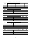
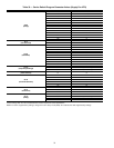
The microprocessor has been programmed to check the op-
eration of the thermistors. If the measured temperature is out-
side of the range of –24 to 225 F or 98,010 to 282 ohms, then it
will be treated as a sensor failure and a diagnostic code will be
displayed. See Table 19 for sensor temperatures versus resis-
tance drop. It is also possible to check the operation of the ther-
mistors using the quick test routine.
If a thermistor has failed or the wire is damaged, replace the
complete assembly. Do not attempt to splice the wires or repair
the assembly.
Electronic Controls Checkout —
The following will
help determine whether a processor board, a relay board, dis-
play set point board, accessory board, or 2-step demand limit
module is faulty.
Before checking out any board, do the following:
1. At initial start-up, enter the Quick Test mode. This test
will determine if all components are connected and oper-
ating properly.
2. If system has been operating and a malfunction occurs,
check display for diagnostic codes. Use diagnostic chart
located on inner panel of access door to control box sec-
tion of unit; this chart will help determine probable cause
of failure.
These 2 steps will help determine if a component other than
a board is at fault or if the problem is external to control circuit.
A volt-ohmmeter will be needed to troubleshoot boards. A
digital meter is preferred but a Simpson 260 or equivalent will
work.
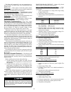
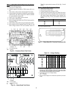
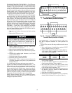
PROCESSOR BOARD CHECKOUT — Refer to Fig. 49 and
50 for location of terminal pins and test points.
Step 1 — Check Transformer Input to the Board
— Con-
nector J4 is used to connect the control transformer to the pro-
cessor board.
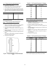
1. Set the volt-ohmmeter to ac voltage with a range setting
of approximately 30 v.
2. Turn control switch to ON position.
3. Check voltage at following terminals on pin terminal con-
nector J4:
4. If voltage is not within range, check primary side.
115-v transformer — 104 to 127 vac
230-v transformer — 207 to 254 vac
5. If primary voltage is not correct, check system fuse, trans-
former, ON-OFF switch, and wiring. If these are okay,
contact power company.
6. If primary voltage is correct, but secondary voltage (24 v
± 10%) is incorrect, replace transformer.
7. Turn control switch to OFF position.
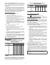
Step 2 — Check Processor Board Power Supply
1. Set meter to approximately 20 vdc.
2. Turn power to OFF position.
3. Connect negative lead to TP18.
4. Turn power switch to ON position and press display but-
ton to enter Quick Test mode.
5. Check voltage between TP18 and each of the following
test pins:
*If not using a digital meter, leads must be reversed.
6. If voltage is incorrect, replace processor board.
7. Turn power to ON position.
Step 3 — Check Voltage Tolerance Circuitry
1. Turn power to OFF position.
2. Negative test probe on TP18 and system in Quick Test
mode.
3. Check voltage TP18 to TP9.
4. If voltage is greater than 11 vdc, recheck transformer in-
put voltage.
5. If transformer is okay, replace processor board.
6. Turn power to ON position.
Step 4 — Check Processor Reset Line
1. Turn power to OFF position.
2. Negative probe on TP18.
3. Check voltage TP18 to TP11.
4. If voltage is greater than +3 vdc, reset power and recheck.
5. If voltage is still incorrect, replace processor board.
6. Turn power to ON position.
To prevent damage to solid-state electronic components on
boards, meter probes should only be placed on terminals
and test points listed in following sections. Do not short the
electrical components, and use extreme care while working
on the processor board.
TERMINALS VOLTAGE (AC)
1 to 2
15.3 to 20.9
4 to 6
16.2 to 22.0
5 to 6
8.1 to 11.0
5 to 4
8.1 to 11.0
TEST PIN VOLTAGE (DC)
TP3
+10
TP4
+12
TP6
+5
TP10
+5
TP14
+12
TP15
+12
TP7
–5*