


35
Operating Sequence —
The sequence presented be-
low assumes that the unit is equipped with heat for morning
warm-up and an economizer. If these items are not enabled
with the appropriate DIP switches, the processor bypasses
these subroutines. This sequence is also based on an EPROM
(erasable, programmable, read-only memory) processor chip
with the identification ‘HT204485-1-XX,’ where ‘XX’ is re-
placed by a 2-digit number representing the current software
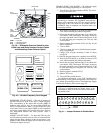
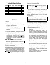
version. See Fig. 1 for EPROM chip location.
When power is applied to the occupied mode relay (OMR)
through the closure of either a field-installed timeclock or a
field-installed switch in the occupied space, the unit will begin
its initialization mode.
A 20 will appear in the display screen, and the initialization
period will last approximately 2 minutes. During this time, the
economizer dampers open and close to determine the resis-
tance range for full economizer operation of the economizer
position potentiometer (P2). The processor loads the necessary
constants for unit operation, and also checks the thermistors
and other potentiometers for their values and validity. After the
initialization period, the screen goes blank until the display but-
ton is pressed.
Once the initialization period is complete, the supply fan be-
gins operation. While the fan is operating, the economizer
dampers are closed and return air from the building is being
circulated. After 2 minutes, the processor checks the resistance
value of thermistor T2. If T2 temperature sensed is 5° F or
more below the set point of the morning warm-up potentiome-
ter (P6), the unit will begin the morning warm-up routine, and
a 26 will be displayed.
Unit heat will be energized through the heat interlock relay
(HIR), and all of the occupied space air terminals will open.
The unit will continue heating the space until the return-air
temperature is within 2° F of set point. The unit will then shut
off the heat and continue to circulate air. The unit will cycle in
and out of the Heating mode until the return-air temperature
reaches the morning warm-up set point (P6). Once morning
warm-up has been terminated, the unit cannot return to morn-
ing warm-up until the unit is powered down and restarted. This
action signals a return to the Occupied mode.
NOTE: Occupied heat is NOT AVAILABLE on these units.
Once out of the morning warm-up routine, the unit will be-
gin its cooling routine based on the supply-air set point (P1). At
step zero, the unit has no mechanical cooling on, and the econ-
omizer may or may not be operational. The economizer will
move to the minimum position determined by potentiometer
P5 if no cooling load is detected. Once a cooling load is detect-
ed by thermistor T1 sensing a temperature higher than the cool-
ing demand set point (P1), the economizer will begin modulat-
ing to meet the load if the outdoor enthalpy is good. The pro-
cessor will attempt to maintain a supply-air temperature of P1
± 2° F by modulating the economizer dampers.
No mechanical cooling will take place until the economizer
dampers are fully open (if the outdoor-air enthalpy permits). If
the economizer is unable to meet the cooling demand, then me-
chanical cooling is used in conjunction with the economizer. If
the economizer is unable to meet the load due to unacceptable
outdoor-air enthalpy, the dampers will return to the minimum
position as determined by P5.
Compressors, unloaders, and condenser fans will be cycled
to maintain a supply-air temperature 2° F below the potentiom-
eter P1 set point once the mechanical cooling stages begin.
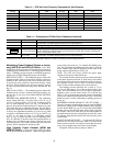
Each unit’s cycling is slightly different, and is based on the
number of compressors and unloaders. The operational loading
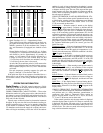
sequence of compressors is as follows:
During the start-up of the lead compressor for each circuit,
the low-pressure switch will be bypassed for 120 seconds to
prevent nuisance trips of the low-pressure switch. After start-
up, a low-pressure trip will be ignored for 30 seconds by the
processor.
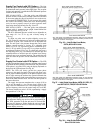
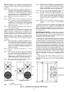
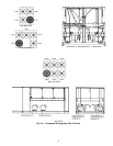
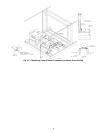
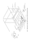
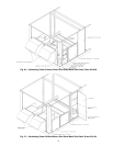
SIZE 034,038 AND 048-088 UNITS — These units have 2
compressors and 2 unloaders on compressor 1. See Fig. 42 and
43 for compressor and condenser-fan motor locations. The
operating sequence is as follows:
Stage 1 Relays K1, K2, and K3 are energized. Compressor
no. 1 starts with both unloaders energized. Compres-
sor no. 1 runs at
1
/
3
capacity. The crankcase heater for
this compressor has been deenergized, and the first
stage of condenser fans have been energized. Out-
door (condenser) fan motor no. 1 (OFM1) has started
on all units.
Stage 2 Relays K1 and K3 are energized. Compressor no. 1 is
running with unloader 1 (U1) energized. The com-
pressor is now operating at
2
/
3
capacity.
Stage 3 Relay K1 is energized. Compressor no. 1 is fully
loaded.
Stage 4 Relays K1, K2, K3, and K5 are energized. Compres-
sor no. 1 is running at
1
/
3
capacity, and compressor
no. 2 is running at full capacity. The crankcase heater
for compressor no. 2 has been deenergized.
Stage 5 Relays K1, K3, and K5 are energized. Compressor
no. 1 is running at
2
/
3
capacity, and compressor no. 2
is running at full capacity.
Stage 6 Relays K1 and K5 are energized. Both compressors
are running fully loaded.
Size 034 and 038 units have 2 condenser fans, one of which
is controlled by the microprocessor. The OFM1 is energized
with compressor no. 1. The OFM2 is controlled by the proces-
sor and is cycled based on input from circuit thermistor T3 or
T4.
Size 048 units have one fan that can be controlled by the
processor. The other 2 are controlled by the compressors. The
OFM1 is energized by compressor no. 1, and OFM3 is ener-
gized by compressor no. 2. The OFM2 is cycled by the proces-
sor based on input from either circuit (thermistors T3 and T4).
On size 054,064 units, the first 2 condenser fans energize
with the compressors; compressor no. 1 controls OFM1, and
compressor no. 2 controls OFM2. The OFM3 and OFM4 are
staged by the microprocessor based on the condensing temper-
ature input from thermistor T3 or T4.
On size 074-078 units, the first 3 condenser fans energize
with the compressors; compressor no. 1 controls OFM1, and
compressor no. 2 controls OFM2 and OFM3. The OFM4 and
OFM5 are staged by the microprocessor based on condensing
temperature input from either circuit’s T3 or T4 thermistor.
On Size 088 units, the first 4 condenser fans energize with
the compressors; compressor no. 1 controls OFM1 and OFM3,
and compressor no. 2 controls OFM2 and OFM4. The OFM5
and OFM6 are staged by the microprocessor based on
condensing temperature input from either circuit’s T3 or T4
thermistor.
Use caution during this time (after initialization when the
screen is blank), because the unit supply and return fans
could start at any time. Personal injury could result from
contact with rotating fans.