


53
STANDARD TRANSDUCER CONTROL — The VFD mon-
itors and controls duct pressure (DP) via a differential pressure
transducer. The pressure transducer is located in the auxiliary
control box (034-048 units) or in the supply fan compartment
(see Fig. 34). The pressure transducer’s low pressure reference
port is connected to the outside of the unit cabinet by a factory-
installed tubing section. The pressure transducer’s high pres-
sure reference point must be field-connected to the duct pres-
sure pick-up (field-supplied and installed in the supply duct).
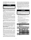
The DP transducer monitors the static pressure in the supply
duct and provides a 4 to 20 mA signal directly to the VFD. (Re-
fer to Table 13 for transducer output signal [mA] for actual duct
static pressure.) The internal logic of the VFD compares this
signal representing actual duct pressure to the user-configured
DP set point. The VFD automatically adjusts its output to the
supply fan motor to maintain the desired DP set point. When
operating with the factory-standard DP transducer, the internal
PID logic of the VFD is enabled. EXTERNAL SIGNAL
CONTROL — If the VFD is to be controlled by an external
control system other than the factory supplied pressure trans-
ducer, the internal PID logic function of the VFD must be dis-
abled. To disable the PID control:
1. Disconnect and lock out all power to the Carrier rooftop
unit.
2. Remove the VFD access cover.
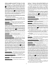
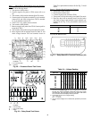
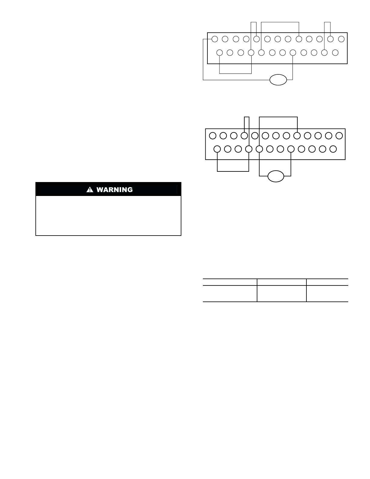
3. Install a jumper across S2-CC (see Fig. 54 and 55 for
VFD terminal board connections).
4. Remove factory-supplied cable attached to IV and CC.
5. Remove other end of the same cable from the pressure
sensor.
6. Connect field supplied speed reference (4 to 20 mA)
across terminals IV-CC.
7. Disable the supply fan motor operation.
8. Reconnect power to the unit and VFD.
9. Reprogram the VFD to accept an external reference (in
the Utility parameters group [Gr.Ut], set parameter item
Fnod [no.312] = 4).
10. Enable supply fan motor and return power to the unit.
SUPPLY FAN MOTOR OVERLOAD PROTECTION — The
VFD provides operating overload protection for the supply fan
motor. The factory has programmed the VFD overload func-
tion to match the factory-installed motor (motor size and effi-
ciency). If the supply fan motor is changed from the original
factory selection, the overload value may need to be changed
by the service person. Contact your local Carrier representative
for assistance in determining the proper overload setting.
NOTE: Variable frequency drive size is matched to factory-
installed motor size. Do not increase motor size without also
changing to equivalent VFD size.
VFD OPERATION — When troubleshooting the VFD, check
first that all required conditions for VFD operation are
satisfied.
For the VFD to run, the following conditions must be met at
the VFD:
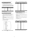
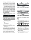
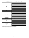
1. Drive enable jumper is installed from terminals CC-ST
(factory supplied) (see Fig. 54 and 55).
2. Proper rotation jumper is installed at terminals R-CC (re-
verse rotation, factory supplied) or terminals F-CC (for-
ward rotation, factory supplied).
3. Emergency stop jumper is installed from terminals
S4-CC (factory supplied).
4. A 4 to 20 mA signal is applied across terminals IV-CC
(from pressure transducer, factory supplied).
5. DIP switch SW1 (located on the VFD’s printed circuit
control panel) must be set to ‘‘I’’ (indicating usage of a 4
to 20 mA input signal at terminals ‘‘IV’’).
6. Speed Control (located on the VFD’s keypad/display) set
for ‘‘Remote’’ (press the ‘‘Speed Ctrl’’ button until LED
‘‘Remote’’ is illuminated).
7. Programmed according to Carrier defaults.
8. Duct Pressure set point established by user, or use factory
default (30 Hz indicating 2.50-in. wg) (see Table 13).
Ensure the “CHARGE” lamp on the VFD is unlit. This
may up to 4 minutes. The “CHARGE” lamp indicates that
the main capacitors in the VFD are charged. Internal com-
ponents of the VFD should not be touched until the
“CHARGE” lamp is completely out. Electrical shock can
cause injury or death.
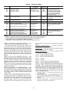
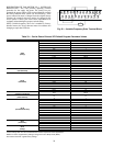
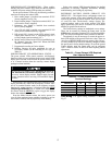
UNIT SIZES ROTATION JUMPER
034-048
Reverse R-CC
054-074
Forward F-CC
078-104
Forward F-CC
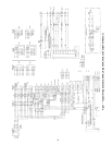
4-20mA
P24
RES
RR
F
ST
FM
AM
CC
CC
R
SI
RX
S2
S3
PP
S4
RCH
P24
LOW
LOW
FLA
FLB
FLC
FP
IV
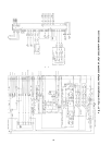
P24
RES
RR
F
ST
FM
AM
CC
CC
R
SI
RX
S2
S3
PP
S4
RCH
P24
LOW
LOW
FLA
FLB
FLC
FP
IV
4-20mA
Fig. 54 — Supply Fan Variable Frequency Drive
Terminal Block (Size 034-048 Units)
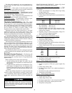
Fig. 55 — Supply Fan Variable Frequency Drive
Terminal Block (Size 054-104 Units)