


52
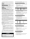
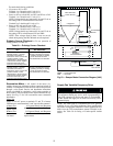
Test under the following conditions:
• No power to IN1 or IN2
Terminal 1 to 2 should read 4.5 vdc ±0.1 v
Terminal 2 to 3 should read 5.0 vdc ±0.1 v
• Power to IN2 or to both IN1 and IN2, and P2 set at 24%
Terminal 1 to 2 should read 1.5 vdc ± 0.1 v
NOTE: Voltage should vary between 0.5 vdc and 2.5 vdc as
the setting of P2 is varied between 0% and 49%.
Terminal 2 to 3 should read 5.0 vdc ± 0.1 v
• Power to IN1 only and P1 set at 50%
Terminal 1 to 2 should read 2.5 vdc ± 0.1 v
Terminal 2 to 3 should read 5.0 vdc ± 0.1 v
NOTE: Voltage should vary between 0.5 vdc and 2.5 vdc as
the setting of P2 is varied between 50% and 100%.
NOTE: If the voltages listed in these 3 tests are not ob-
tained during testing, the DLCM board must be replaced.
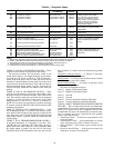
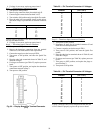
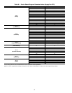
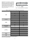
Enthalpy Sensor Checkout —
To test operation of
enthalpy sensor, see Table 29.
Table 29 — Enthalpy Sensor Checkout
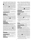
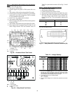
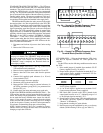
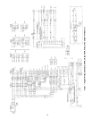
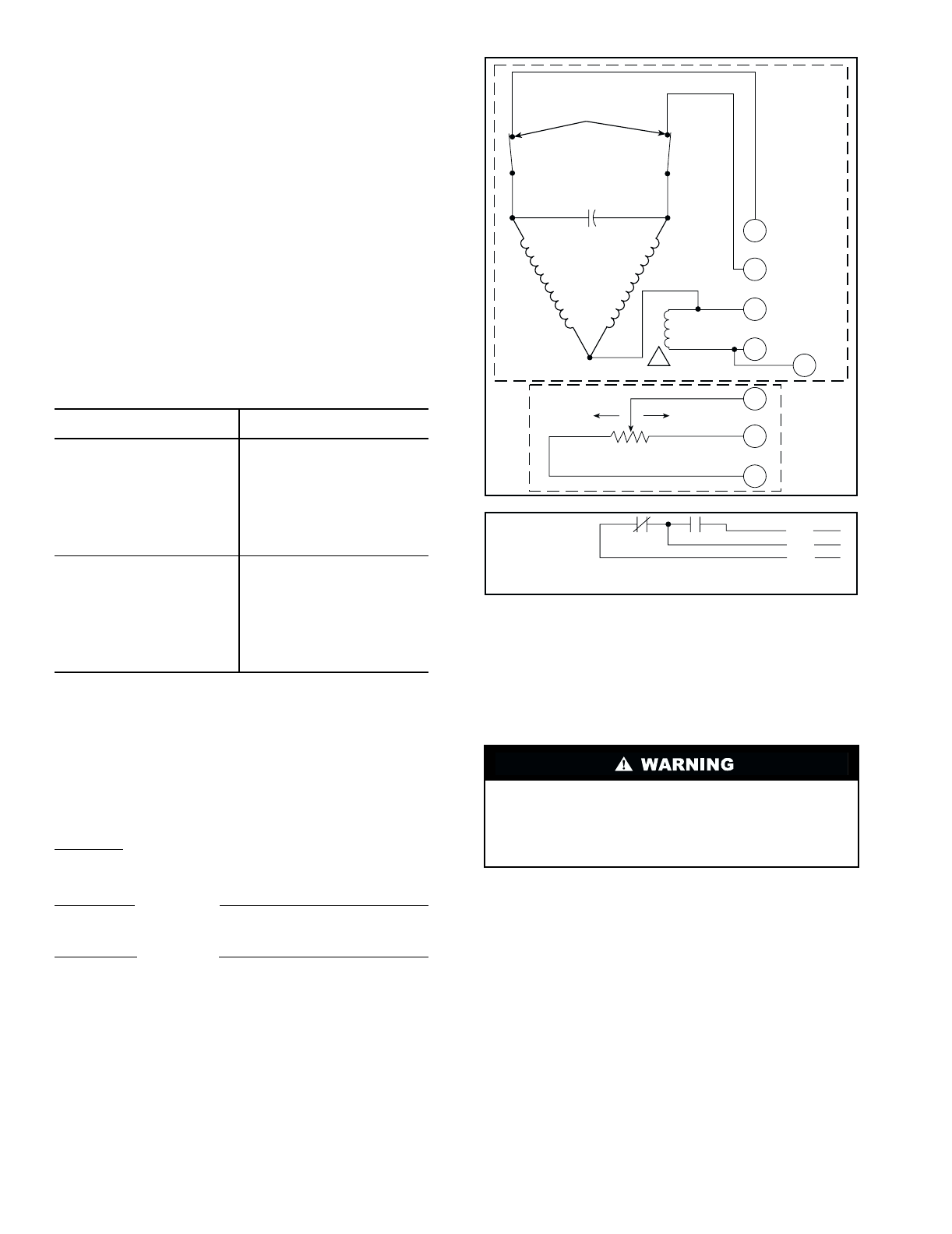
Economizer Motor —
All control of the motor (i.e.,
enthalpy changeover, minimum position control and mixed air
control) is accomplished from the main unit microprocessor
through a relay board. Service and installation instructions
for the unit should be consulted to verify proper operation of
these controls. The economizer motor may be checked out sep-
arately. See Fig. 52 for VAV economizer motor connection
information.
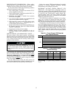
Motor Test
Apply 24 volt AC power to terminals T1 and T2 of motor.
Connections to motor terminals 2 and 3 must be disconnected
A Motor Test
A Expected Result and Response
Jumper 1 to Motor drives open; if not, 2 at motor
replace motor.
B Motor Test
B Expected Result and Response
Jumper 1 to Motor drives closed; if not,
3 at motor replace motor.
Supply Fan Variable Frequency Drive
NOTE: The VFDs (part no. TOSVERT130-E3) are specially
modified for use on Carrier equipment. Some specifications
and control configuration defaults for Carrier applications will
differ from the VFD manufacturer manual included in the
packet. See Table 30 for listing of Carrier-specific default
values.
TEST
EXPECTED RESULT
AND RESPONSE
Outdoor-air sensor:
Enthalpy sensor + terminal
should be connected to +
terminal on motor. Connect the
positive terminal of a DC
milliammeter to the S terminal
of the sensor and the negative
terminal of the meter to S
O
terminal of the enthalpy board.
Milliammeter reading should be
between 3 and 24 mA if sensor
is operating correctly. If reading
is 0 mA, the sensor is either
wired backwards or is defective.
Indoor-air sensor:
Enthalpy sensor + terminal
should be connected to +
terminal on motor. Connect the
positive terminal of a DC
milliammeter to the S terminal
of the sensor and the negative
terminal of the meter to S
R
terminal of the enthalpy board.
Milliammeter reading should be
between 3 and 24 mA if sensor
is operating correctly. If reading
is 0 mA, the sensor is either
wired backwards or is defective.
Factory-installed optional VFD is located near the supply
fan and motor. During any service work or programming at
the VFD, operation of the fan and motor is not desirable.
Either disable the supply fan or install an accessory VFD
remote display.
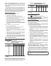
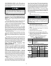
BLU
RED
YEL
AUX. SWITCH
LIMIT SWITCHES
CAPACITOR
CW
WINDING
(OPEN)
CCW
WINDING
(CLOSE)
CW
FEEDBACK
POTENTIOMETER
ECONOMIZER
MOTOR
BRAKE
WINDING
1
3
2
T1
T2
1
1
2
3
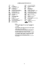
LEGEND
Fig. 53 — Damper Motor Connection Diagram (VAV)
CCW —
Counterclockwise
CW —
Clockwise