


2
CONTENTS (cont)
Page
TROUBLESHOOTING
. . . . . . . . . . . . . . . . . . . . . . . . . 44-60
Checking Display Codes
. . . . . . . . . . . . . . . . . . . . . . . . 44
Complete Unit Stoppage
. . . . . . . . . . . . . . . . . . . . . . . . 44
Single Circuit Stoppage
. . . . . . . . . . . . . . . . . . . . . . . . . 44
Restart Procedure
. . . . . . . . . . . . . . . . . . . . . . . . . . . . . . . 45
Diagnostic Codes
. . . . . . . . . . . . . . . . . . . . . . . . . . . . . . . 45
• CODES 51, 52, 55, 56: COMPRESSOR FAILURE
• CODES 59 AND 60: LOW-PRESSURE SWITCH
• CODES 63 AND 64: OIL PRESSURE SWITCH
• CODE 70: ILLEGAL UNIT CONFIGURATION
• CODES 71 TO 76: THERMISTOR/RESISTOR
FAILURE
• CODE 81: RESET THERMISTOR OR
POTENTIOMETER FAILURE
• CODE 82: SUPPLY-AIR TEMPERATURE SET POINT
POTENTIOMETER FAILURE
• CODE 83: ECONOMIZER FEEDBACK
POTENTIOMETER FAILURE
• CODE 84: RESET LIMIT POTENTIOMETER
FAILURE
• CODE 85: DEMAND LIMIT POTENTIOMETER (P4)
FAILURE
• CODE 86: MINIMUM POSITION ECONOMIZER
POTENTIOMETER FAILURE
• CODE 87: WARM-UP TEMPERATURE SET POINT
FAILURE
Thermistor Troubleshooting
. . . . . . . . . . . . . . . . . . . . . 48
Electronic Controls Checkout
. . . . . . . . . . . . . . . . . . . 48
• PROCESSOR BOARD CHECKOUT
• RELAY BOARD TROUBLESHOOTING
• DISPLAY BOARD CHECKOUT
• ACCESSORY BOARD CHECKOUT
• TWO-STEP DEMAND LIMIT CONTROL MODULE
(DLCM) TROUBLESHOOTING
Enthalpy Sensor Checkout
. . . . . . . . . . . . . . . . . . . . . . 52
Economizer Motor
. . . . . . . . . . . . . . . . . . . . . . . . . . . . . . . 52
Supply Fan Variable Frequency Drive
. . . . . . . . . . . 52
• STANDARD TRANSDUCER CONTROL
• EXTERNAL SIGNAL CONTROL
• SUPPLY FAN MOTOR OVERLOAD PROTECTION
•VFD OPERATION
• VFD OPERATIONAL STATUS
• RESTORING FACTORY VFD DEFAULTS
Power Exhaust Variable Frequency Drive
. . . . . . . 55
• STANDARD TRANSDUCER CONTROL
• EXTERNAL SIGNAL CONTROL
• POWER EXHAUST FAN MOTOR NO. 1 OVERLOAD
PROTECTION
• POWER EXHAUST VFD OPERATION
• POWER EXHAUST VFD OPERATIONAL STATUS
• RESTORING FACTORY POWER EXHUAST VFD
DEFAULTS
Unit Wiring
. . . . . . . . . . . . . . . . . . . . . . . . . . . . . . . . . . . . . . 57
START-UP CHECKLIST
. . . . . . . . . . . . . . . . . . CL-1, CL-2
SAFETY CONSIDERATIONS
Installing, starting up, and servicing this equipment can be
hazardous due to system pressures, electrical components, and
equipment location (roof, elevated structures, etc.). Only
trained, qualified installers and service mechanics should in-
stall, start up, and service this equipment.
When working on this equipment, observe precautions in
the literature; on tags, stickers, and labels attached to the equip-
ment, and any other safety precautions that apply. Follow all
safety codes. Wear safety glasses and work gloves. Use care in
handling, rigging, and setting this equipment, and in handling
all electrical components.
GENERAL
Carrier 48FK,FM,JK and 50FK,FM,FS,FY,JK,JY units pro-
vide ventilation, cooling, and heating (when equipped) in Vari-
able Air Volume (VAV) applications. These units contain facto-
ry-installed controls which provide full system management.
The unit controls also perform self diagnostic tests at unit start-
up, monitor operation of the unit, and provide alarms. Informa-
tion on system operation and status are sent to the central pro-
cessors by various sensors that are located at the unit and in the
conditioned space. Each unit is equipped with a display board.
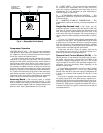
Rooftop Information —
The rooftop controls cycle
supply-fan motor, compressors, and unloaders to maintain the
proper temperature conditions. The controls also cycle con-
denser fans to maintain suitable head pressure. Safeties are
continuously monitored to prevent the unit from operating un-
der abnormal conditions. The controls provide control of econ-
omizer and cycle or control heating as required.
The controls also allow the service person to operate a
‘quick test’ so that all the controlled components can be
checked for proper operation.
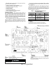
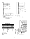
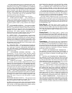
VAV Control System —
The 30 to 100-ton VAV roof-
top units contain a microprocessor-based electronic control
system that controls and monitors the rooftop unit functions.
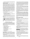
The VAV control system is composed of several components:
• processor board
• relay board
• display board
• thermistors
• compressor operation feedback (control relay)
• accessory board
• temperature reset package*
• single-step demand limit*
• two-step demand limit control module*
*Field-installed accessories.
Electrical shock can cause personal injury and death. Shut
off all power to this equipment during installation and ser-
vice. There may be more than one disconnect switch. Tag
all disconnect locations to alert others not to restore power
until work is completed.
This unit uses a microprocessor-based electronic control
system. Do not use jumpers or other tools to short out com-
ponents, or to bypass or otherwise depart from recom-
mended procedures. Any short-to-ground of the control
board or accompanying wiring may destroy the electronic
modules or electrical components.
IMPORTANT: This literature contains controls, opera-
tion, and troubleshooting data for 48FK,FM,JK and
50FK,FM,FS,FY,JK,JY variable air volume rooftop
units. Use this guide in conjunction with the separate
Installation Instructions literature packaged with the
unit.
IMPORTANT: The field-supplied and installed switch
(or timeclock) MUST BE CLOSED to put unit into the
Occupied mode. Unit WILL NOT START until this is
accomplished. See base unit installation instructions lit-
erature for details.